Braking Resistor Connection
Connecting the External Braking Resistor o Verify that no voltages are present o Remove the cover from the connection o Ground the ground connection (PE) of the braking resistor o Connect the external braking resistor to the device Note the tightening torque specified for the terminal screws o Connect the cable shield to the shield connection at the bottom of the device (large surface.
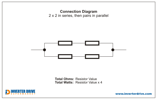
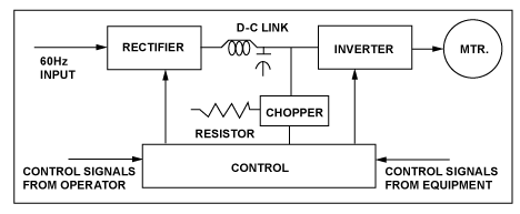
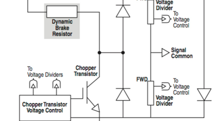
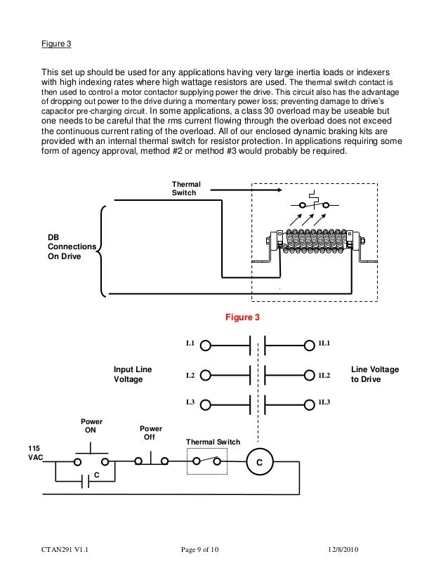
Braking resistor connection. Dynamic Braking Resistors (DBR)– When the AC motor has to be brought to a stop, the VFD with the aid of the braking resistor acts like an electrical braking system instead of employing mechanical braking The excess energy present in the rotating system has to be dumped somewhere quickly and that is the basic function of the Dynamic Braking. The third is to apply an electrical "brake" via a regenerative variable frequency drive (VFD) and/or dynamic braking resistor Essentially, the dynamic braking resistor is a dumping ground for the energy contained in the rotating system, allowing it to be "bled off" as electrical energy Because the operational mode has changed from motoring. Resistor converts the consume energy into heat and at the same instant braking effect is created Hence, the resistor used in this process is known as braking resistor and the process is called dynamic braking Thus, the purpose of a braking resistor is to quickly stop or slow down the mechanical system by producing a braking torque.
Braking Module contains the power electronics and the associated Control Unit The supply voltage for the electronics is drawn from the DC link During operation, the DC link energy is converted to heat loss in an external braking resistor The Braking Module functions independently of the converter closedloop controller In the. The property of resistors to dissipate heat can be used to slow down a mechanical system This process is called dynamic braking and such a resistor is called a dynamic braking resistor To decelerate an electric motor, kinetic energy is transformed back into electrical energy This energy is dissipated by using a power resistor. Braking Resistor Installation The final consideration when selecting a braking resistor is to ensure that it is installed properly If a braking resistor is not installed according to UL standards, the circuit can fail in a manner that is a fire hazard More information on safe connection of a braking resistor can be found here.
Braking Resistor Connection in VFD Why we Use Braking Resistor In Drive?. Braking resistor connection 4 Revision – MOVIAXIS® MMD60B 3 Electrical installation 31 Braking resistor connection 311 Braking resistor cables WARNING Electric shock from dangerous DC voltage levels in the braking resistance cable (ap prox 900 V) Severe or fatal injuries • The braking resistor cable must be suited for this high DC. The range of uses in connection with drive technology is almost neverending;.
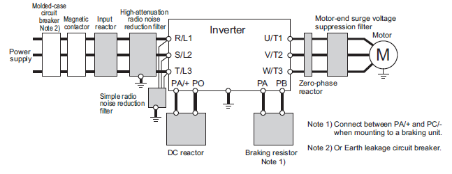
The resistors are connected to DC bus circuit of an inverter, consumes the regeneration power from a motor, and is made to generate braking torque from the motor For the small capacity inverters, a compact size and a light weight for the braking resistor units are realized by adopting noncombustible cement resistors. The brake chopper is an extra IGBT mounted into the NX AC drives at the time of manufacturing Smaller AC drives (FR4 to FR6 and MF4 to MF6) contain it as standard If the DC link voltage increases too much, the brake IGBT turns on and discharges the capacitors through the brake resistor The brake chopper in the NX AC drive ranges is rated for. Provide an external brake, etc, as necessary to secure the motor Note that the purpose of motor with brake is holding and it cannot be used for braking application When parameter Pr510 Sequence at alarm is set to free run (disable dynamic brake), the motor is free run state and requires longer stop distance even if no external force is applied.
Pull wiring into the enclosure for connection to resistor Braking amps are listed on the drawing for correct wire sizing If connecting directly to the terminals on the resistor elements, it is necessary to use high temperature silicon or teflon wire rated 0ºC Try to route wiring along the bottom of the. The braking resistor is connected to the Braking Module The distance between the Braking Module and braking resistor must not exceed 100 m This enables the resulting heat loss to be dissipated outside the switchgear room Resistors with rated powers of 25 kW and 50 kW are available. Filter and braking resistor, connection option for external braking resistor • Precise torque, speed and position control • Motion from pointtopoint to interpolated motion • Comprehensively integrated protective functions for the servo drive, motor and.
3 Installing the external chassis braking resistor The braking resistor must be mounted correctly on the wall or the mounting surface close to the frequency inverter in vertical position with the 4 fastening screws which are provided Permissible Not permissible 4 Connection cable (BR TS) Connect braking resistor to the frequency inverter. The materials near the braking resistor must be nonflammable The surface temperature of the resistor may rise above 0 °C (400 °F), and the temperature of the air flowing from the resistor is hundreds of degrees Celsius Protect the resistor against contact The maximum length of the resistor cable(s) is m (65 ft) For the connections,. Braking resistor connection 4 Revision – MOVIAXIS® MMD60B 3 Electrical installation 31 Braking resistor connection 311 Braking resistor cables WARNING Electric shock from dangerous DC voltage levels in the braking resistance cable (ap prox 900 V) Severe or fatal injuries • The braking resistor cable must be suited for this high DC.
Braking time should be limited to under 10% of total cycle time This gives the braking resistor enough time to dissipate the heat that is generated during braking If the braking cycle increases higher than this threshold, then the VFD is at risk of burning the DBR This could lead to damage of the Braking Unit and the VFD. MFPR Braking Resistor with power from 50W to 15kW Customizable *connection *mounting *IP65 *Thermal Switch *low Inductance Prompt Delivery & Good price. The materials near the braking resistor must be nonflammable The surface temperature of the resistor may rise above 0 °C (400 °F), and the temperature of the air flowing from the resistor is hundreds of degrees Celsius Protect the resistor against contact The maximum length of the resistor cable(s) is m (65 ft) For the connections,.
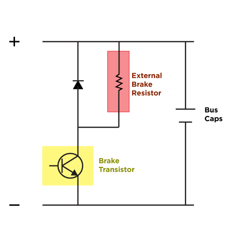
So for example if the max DC bus level was 800V and the resistor value was 8ohms, then 10A would flow through the resistor and a #14, cable would be sufficient?. For dynamic braking you need the transistor to turn on only when the DC bus voltage gets above a certain level, then the energy gets sent to the resistor for dissipation Afterward, the connection needs to be broken once the bus voltage drops back within normal limits. A Braking Module (and an external braking resistor) is required in certain cases when the drive is to be braked or brought to a standstill (eg, EMERGENCY STOP category 1) The Braking Module contains the power electronics and the associated Control Unit The supply voltage for the electronics is drawn from the DC link.
A braking resistor can be used to dissipate the unwanted electrical energy There are some purposebuilt units for this duty, engineered for roomless lifts and for fitting inside the framework of an escalator These resistors have special EMC connection boxes which are required in public buildings and can provide protection against damp and dust. 1370 Dynamic Braking Resistors Installation Using Table 1 , locate the appropriate dimension and connection diagrams Table 1 Dynamic Braking Resistor Kits Hp Basic Catalog Number Dimension Drawing Connection Diagram Total Watts Total Resistance (Ohms) Watts Per Resistor 240V DC Motor Armature Voltage 1 1370DBL61 1 A 325 360 325 x 1. If a brake resistor was not used, the intermediate circuit voltage of the frequency converter would continue to increase, until it cuts out for protection The advantage of using a brake resistor is it enables braking of a heavy load quickly, eg on a conveyor belt.
Pull wiring into the enclosure for connection to resistor Braking amps are listed on the drawing for correct wire sizing If connecting directly to the terminals on the resistor elements, it is necessary to use high temperature silicon or teflon wire rated 0ºC Try to route wiring along the bottom of the. Hence for large motors brake can be applied via an external high wattage low value resistor For energy conscious designs, the motor can be braked by an charging circuit (regenerative braking) in which the energy is not dissipated but recovered and can be used later Motor can be braked by an inverter as such. Is high temp wire typically recommended for this connection?.
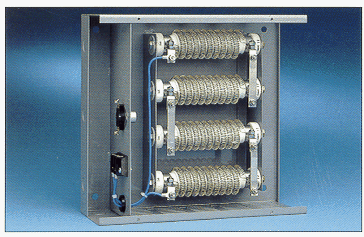
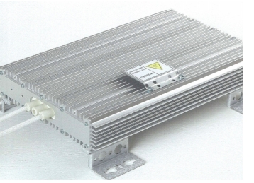
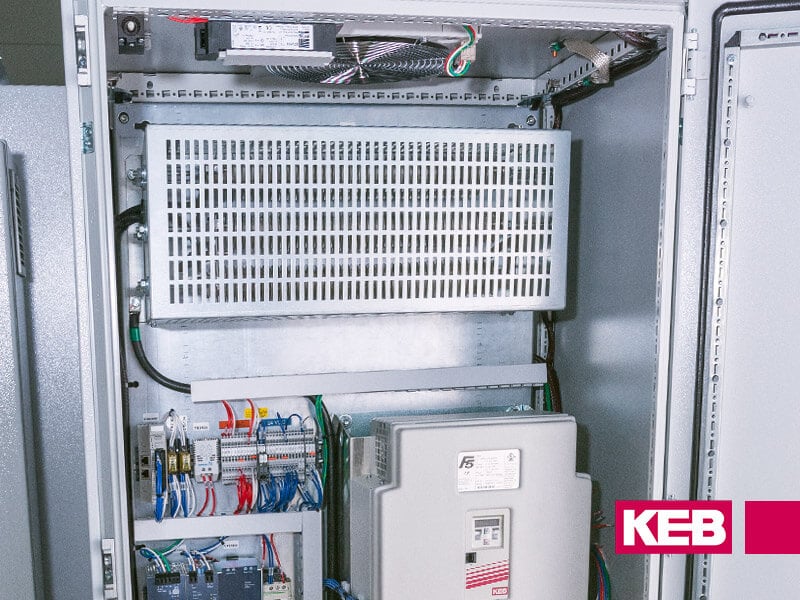
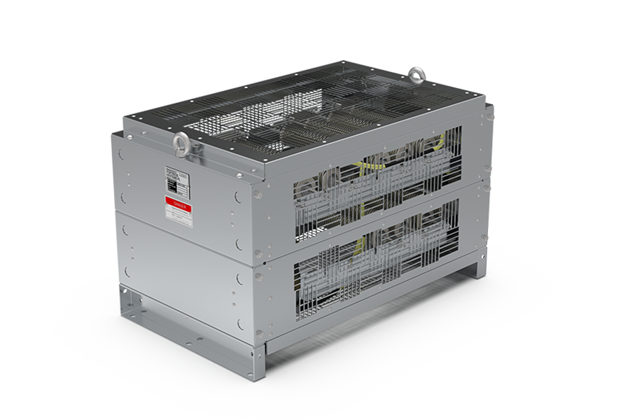
Dynamic Braking Resistors are used with AC VFD’s to produce a braking torque in the motor during overhauling conditions The dynamic braking resistor is connected across the DC bus and will see voltages as high as 800 volts The drive manufacturer normally determines the power rating (watts) needed to prevent overheating during braking duty. A Braking Resistor is a power resistor that absorbs and dissipates as heat, this is extra energy thus slowing down or “braking” the motor This is often referred to as “Dynamic Braking” and is very useful in safely controlling motor stops, increasing efficiency and lessening mechanical wear and tear. The braking resistor REOHM 154 protects the machine from a voltage rise in the intermediate circuit, if an electric machine operates as a generator (Electromotive brake) The current reduces also the speed of the machine The serie REOHM 154 is available as braking resistor (series BW) or as charging resistor (series R).
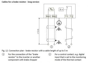
If an unsuitable braking resistor is used, this could result in a fire and severely damage, people, property and equipment Use the adequate braking resistor and install it correctly The temperature of a braking resistor increases significantly during operation Avoid coming into direct contact with braking resistors Repair WARNING. For connection of the external braking resistor to the NORDAC PRO SK 5xxE a temperature switch is available for temperature monitoring The normally closed contact T1/T2 is connected via a free digital input of the frequency inverter We recommend to parametrise the digital input with the Voltage Disable function. Joined 12/10/12 Last visit 11/18/ Posts 1 Rating (0) Hi i am looking for part numbers for a Micromaster 440 braking resistor i need a braking resistor for a MM440 with a 50 % duty cycle.
Is high temp wire typically recommended for this connection?. 613 Parallel connection Two braking resistors with the same value must be connected in parallel for some inverter/resistor combinations In this case, the tr ip current must be set on the bimetallic Braking resistor type BWT/P BW106T BW6T BW BW0034T Part number 10 0 4 10 412 0 1330 152 7 1330 124 5 Continuous. A Braking Resistor is a power resistor that absorbs and dissipates as heat, this is extra energy thus slowing down or “braking” the motor This is often referred to as “Dynamic Braking” and is very useful in safely controlling motor stops, increasing efficiency and lessening mechanical wear and tear.
When setting up the brake resistor on the drive do you need to set the duty cycle of the chopper on the drive?. 2 The value shown for the minimum connection resistance is that for a single braking unit Select a resistance value higher than the connectable resistance value and enough to generate the required braking torque 3 Single = 1 resistor per package Dual = 2 resistors per package (requires 2 DB transistor modules, as indicated in table above). Connection Diagram of Dynamic Braking of DC Shunt Motor In this kind of braking, the dc shunt motor is detached from the power supply & a braking resistor (Rb) is connected across the armature So this motor will function as a generator to generate the braking torque.
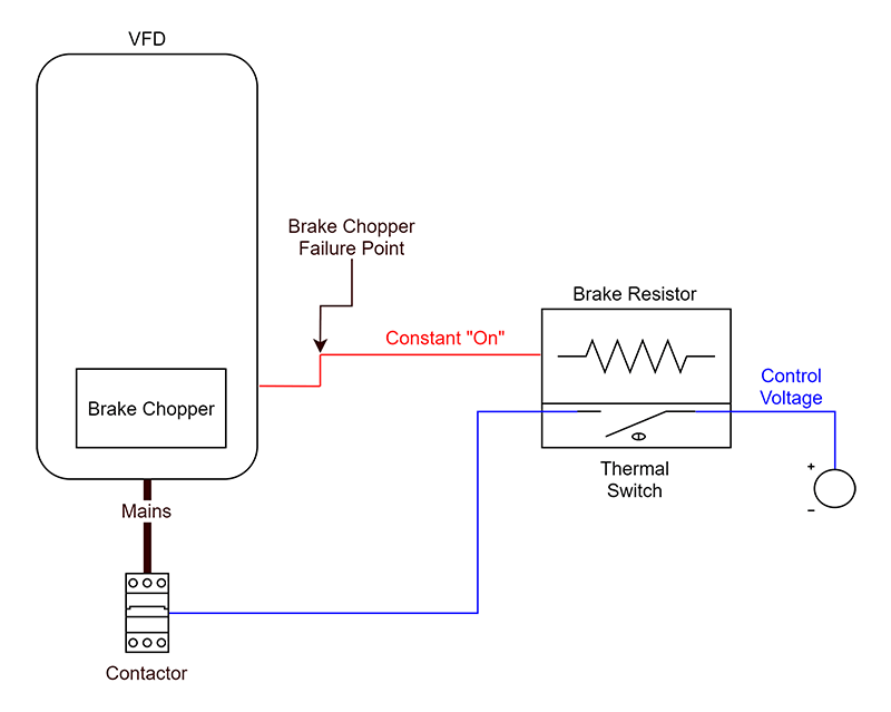
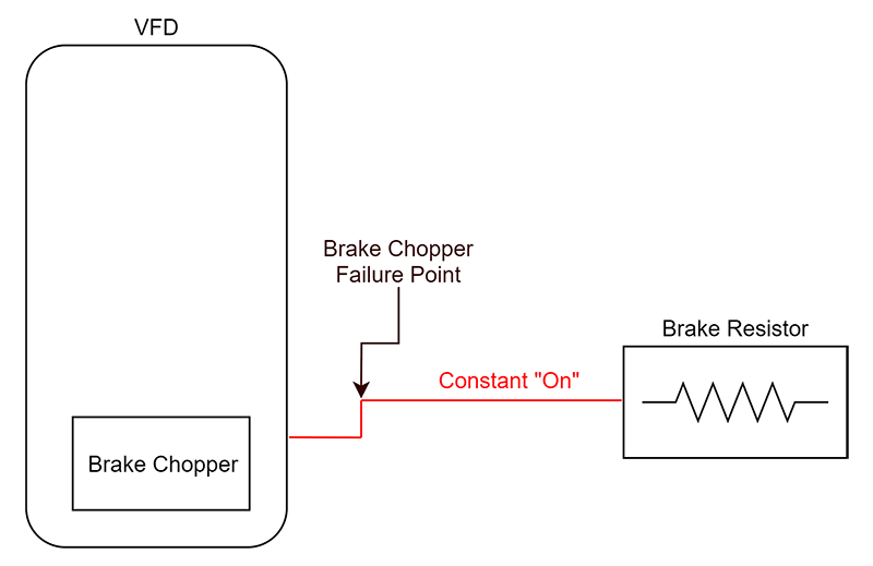
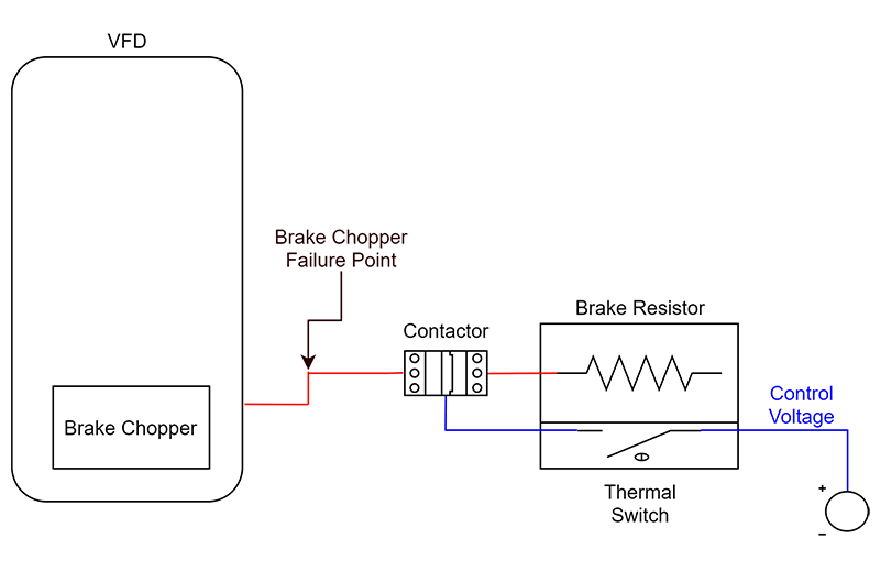
During a shortcircuit failure, the brake resistor is subsequently connected, unrestricted, to the DC bus voltage of the VFD As mentioned earlier, the brake resistor is sized to be used with a chopper circuit Consequently, a direct connection to the DC bus overloads the brake resistor and can cause external damage and also become a fire hazard. Dynamic Braking Resistors are used with AC VFD’s to produce a braking torque in the motor during overhauling conditions The dynamic braking resistor is connected across the DC bus and will see voltages as high as 800 volts The drive manufacturer normally determines the power rating (watts) needed to prevent overheating during braking duty. I purchased a braking resistor 128 ohm/874W and was going to connect to the VFD, but the manual shows a braking unit between the VFD and resistor What is the purpose of polarity on the resistor terminals for a DC connection?.
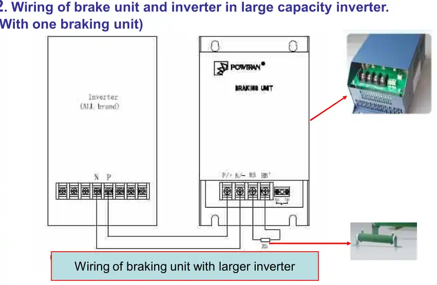
A braking resistor helps to slow down or stop a motor by dissipating excess voltage generated by the decelerating motor When power is removed from a motor, the load is reduced causing it to turn at a faster rate. 4) Braking unit terminal BR,BR connect to braking resistor 5) Make sure all the braking unit JP1 (voltage selection) is selected correctly, and then the parallel connection braking units start level will coincide Braking unit and braking resistor unit application list INVERTER Braking Unit Braking Resistor. Connecting the External Braking Resistor o Verify that no voltages are present o Remove the cover from the connection o Ground the ground connection (PE) of the braking resistor o Connect the external braking resistor to the device Note the tightening torque specified for the terminal screws o Connect the cable shield to the shield connection at the bottom of the device (large surface.
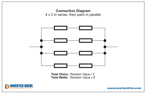
Filter and braking resistor, connection option for external braking resistor • Precise torque, speed and position control • Motion from pointtopoint to interpolated motion • Comprehensively integrated protective functions for the servo drive, motor and. Brake Resistor Calculator Instructions for use Enter the Minimum Brake Resistor Ohms required by the Inverter Leave the Watts entry blank (or enter a value if you prefer to reduce the options) The calculator will list the best combinations of resistors and connection arrangements. So for example if the max DC bus level was 800V and the resistor value was 8ohms, then 10A would flow through the resistor and a #14, cable would be sufficient?.
I can add resistors if needed to reduce the ohms I will make sure my next VFD includes a braking control within the. Wiring between the drive and braking module should not exceed 15 feet and between the braking resistor and braking module should not exceed 30 feet Important Always properly ground each component to earth For best noise immunity connect Braking Module chassis ground directly to AC Drive Module Power earth. Braking Resistor Working in VFD How Braking Resistor works?Braking resistors are u.
The brake resistor is selected on the basis of the AFD rating, the magnitude of the energy to be dissipated, and the braking duty cycle The compact NEMA 1 Use the following for the connection of the dynamic braking resistors for all frame sizes Table 4 Series 9000 Drive Terminal Designations Frame Size. A resistor is a resistor, but there are 2 issues at hand 1) The resistance value (ohms) This is what you need from the VFD manufacturer If you use the wrong size you will either get inadequate braking, or you may damage the braking transistor if it pulls too much current 2) The wattage rating. When setting up the brake resistor on the drive do you need to set the duty cycle of the chopper on the drive?.
The third is to apply an electrical "brake" via a regenerative variable frequency drive (VFD) and/or dynamic braking resistor Essentially, the dynamic braking resistor is a dumping ground for the energy contained in the rotating system, allowing it to be "bled off" as electrical energy Because the operational mode has changed from motoring. Braking resistor unit and braking unit are used to consume regenerative energy from motor in the braking resistor unit at deceleration and to improve the transistor inverter braking ability Before using the braking resistor unit and braking unit, a thorough understanding of this manual is recommended This inst ruction manual will be. The brake chopper is an extra IGBT mounted into the NX AC drives at the time of manufacturing Smaller AC drives (FR4 to FR6 and MF4 to MF6) contain it as standard If the DC link voltage increases too much, the brake IGBT turns on and discharges the capacitors through the brake resistor The brake chopper in the NX AC drive ranges is rated for.
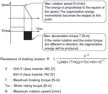
Dynamic braking is the use of an electric traction motor as a generator when slowing a vehicle such as an electric or dieselelectric locomotiveIt is termed "rheostatic" if the generated electrical power is dissipated as heat in brake grid resistors, and "regenerative" if the power is returned to the supply lineDynamic braking reduces wear on frictionbased braking components, and. Braking resistors are normally sized for the average power dissipation over the braking cycle time Maximum braking power Where V brake = Voltage during braking R = Dynamic Breaking Resistor rating (ohms) Braking Torque Combine equations above and Torque braking is the effective braking torque created by the electric motor Torque is in. Braking Resistor terminal layouts Terminals FSA Braking Resistor Max terminal torques (Nm) 05 05 05 05 05 05 05 05 05 05 08 08 08 05 05 Terminals FSB Braking Resistor Terminals FSC Braking Resistor PE DCP/ R1 R2 T1 T2 PE DCP/ R1 R2 T1 T2 PE DCP/ R1 R2 T1 T2 Connection diagram and dimensions %UDNLQJ UHVLVWRU 6KLHOG FRQQHFWLRQ.

Dynamic Braking Resistor Wiring Diagram 147 19 Jan Scarbrough Enotecaombrerosse It

Practical Machinist Largest Manufacturing Technology Forum On The Web

Dynamic And Regenerative Braking
Braking Resistor Connection のギャラリー

Braking Resistor Connection In Vfd Use Of Braking Resistor In Vfd How Braking Resistor Work In Vfd Youtube
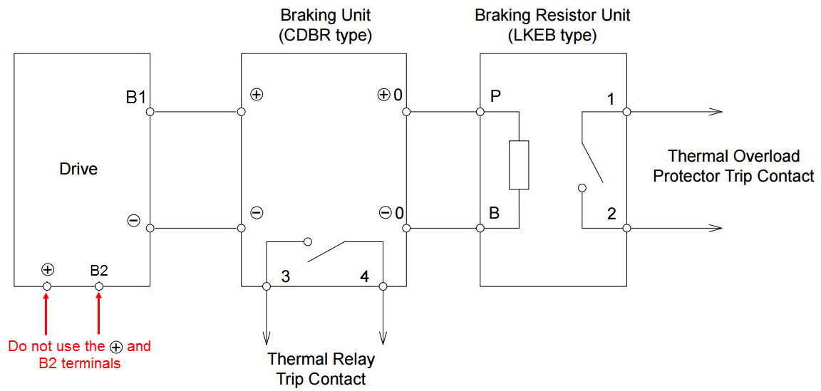
Dynamic Braking Resistor Wiring Diagram 07 Dodge Charger Fuse Box Diagram Podewiring Tukune Jeanjaures37 Fr
Braking Module In Booksize Format Industry Mall Siemens China

Braking Resistor To Dissipate Excess Motor Energy Captech
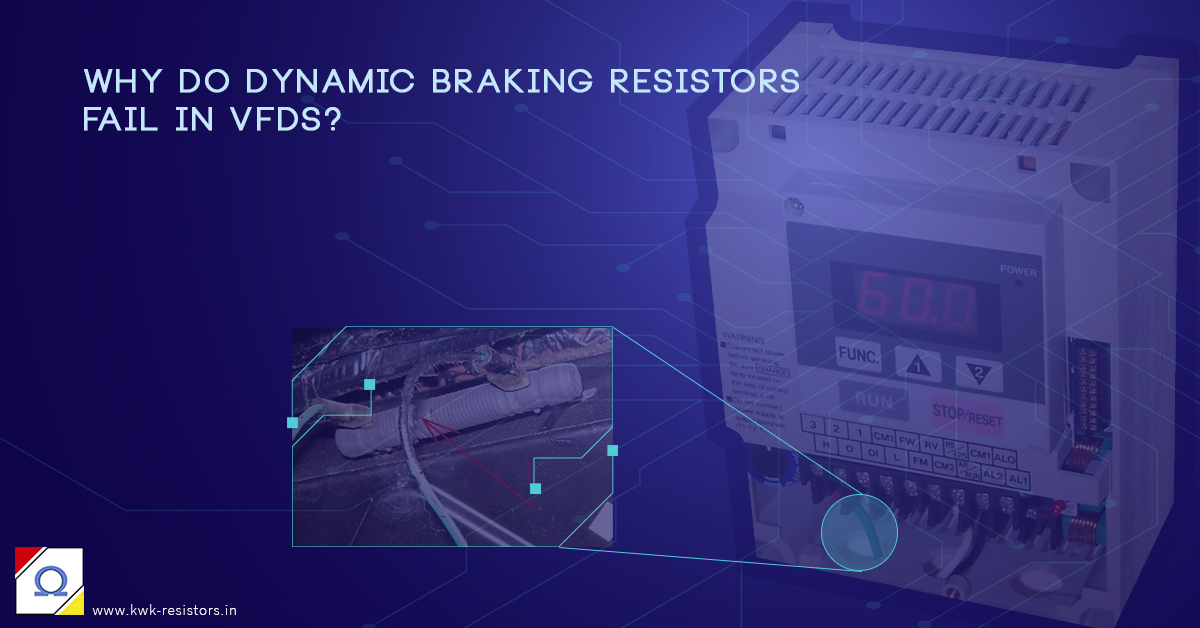
Why Do Dynamic Braking Resistors Fail In Vfds How To Avoid It

Powerflex Dynamic Braking Resistor Calculator Pdf Free Download
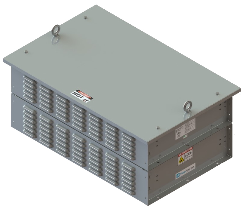
Braking Resistor Megaresistors

Braking Resistor Box Eldis Ehmki Schmid Ohg
Hubbellcdn Com Installationmanuals Powerohm Brakingmod Lg S Pdf
Dynamic Braking Resistors Post Glover Resistors
3 Ways To Protect A Vfd Braking Resistor From Short Circuit Failure Keb
Dynamic Braking Resistors Post Glover Resistors
Inverter Drive Supermarket Brake Resistor Calculator
What Are Brake Resistors Braking Resistor Solutions Es Components A Franchised Distributor And Manufacturer
When And How Should I Select A Braking Resistor Manufacturingtomorrow
Vfd Wiring Home Model Engine Machinist

Inverter Drive Supermarket Brake Resistor Calculator
1

Sir Brr1k0 Braking Resistor Jordan Anwar Est

Inverter Drive Supermarket Brake Resistor Calculator

3g3rx2 High Function General Purpose Inverters Lineup Omron Industrial Automation

Vw3m9010 Connection Module For External Braking Resistor Schneider Electric Global

Diagram In Pictures Database Dynamic Braking Resistor Wiring Diagram Just Download Or Read Wiring Diagram Online Casalamm Edu Mx

Faq What Is Dynamic Braking And When Is It Used
3 Ways To Protect A Vfd Braking Resistor From Short Circuit Failure Keb
Www Nord Com Media Documents Datasheets Ti Sk Br2 9 20 En 45 Desk Pdf
Http Www Hitachi America Us Supportingdocs Forbus Inverters Support Hitachi Dynamic Hbu Series Braking Unit Instruction Manual Pdf

Faq What Is Dynamic Braking And When Is It Used

Optional Devices Toshiba Inverter Tosvert Vf Series

Braking Chopper Wikipedia

What Are Brake Resistors Braking Resistor Solutions Es Components A Franchised Distributor And Manufacturer
Q Tbn And9gcsvpqlptao4txswazmgn1av9eo3usllqdrn2zlh Cvyt7pnn7hl Usqp Cau

Sizing A Shunt Resistor For Regenerative Braking Ingenia Servo Drives
Http Www Deltronics Ru Images Manual Vfdb 4110 4160 4185 I En Pdf

Electrical Installation Wiring Of External Brake Resistor Erbm Lenze Ecsdexxx User Manual Page 97 170
When And How Should I Select A Braking Resistor Manufacturingtomorrow

Femina Instruments Pvt Ltd
Basic Line Modules In Booksize Format Industry Mall Siemens Hongkong
Www Danotherm Com Download 18 445bfda2b713eb2 A brake resistor perspective on voltage ratings Pdf
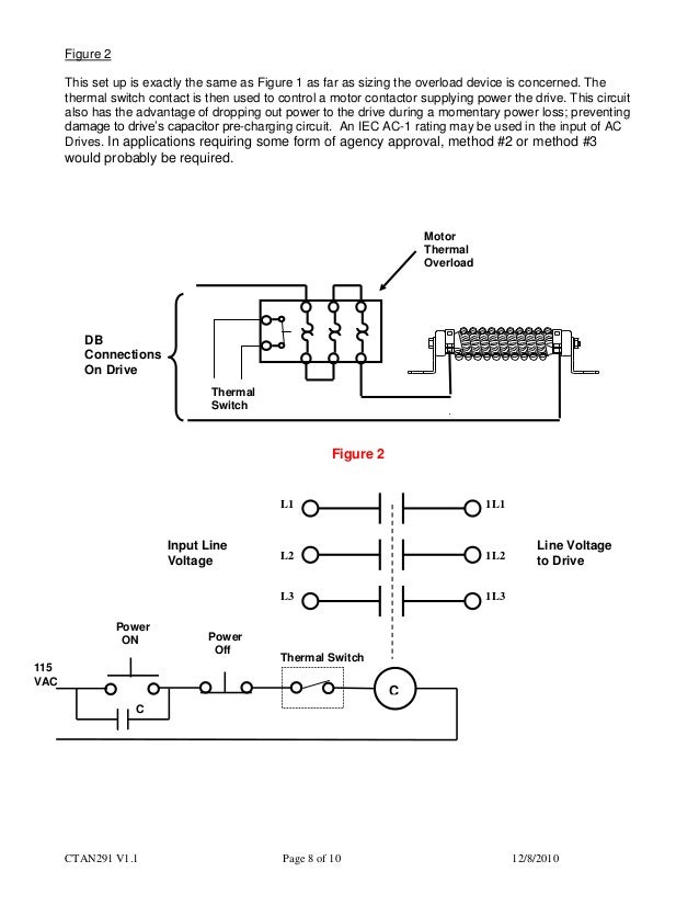
Dynamic Braking Resistor Selection Calculation
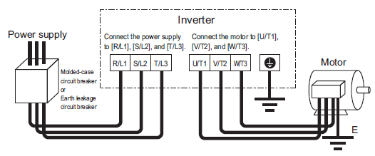
Connection Equipment Toshiba International Corporation
Http Www Hitachi America Us Supportingdocs Forbus Inverters Support Hitachi Dynamic Hbu Series Braking Unit Instruction Manual Pdf
Q Tbn And9gcqdlcpf94vbvrtrwkuchdh3lmcmbveii7 Drs6tgk63mad08 Lp Usqp Cau

Optional Devices Toshiba Inverter Tosvert Vf Series

Motor And Shunt Braking Resistor Pluto
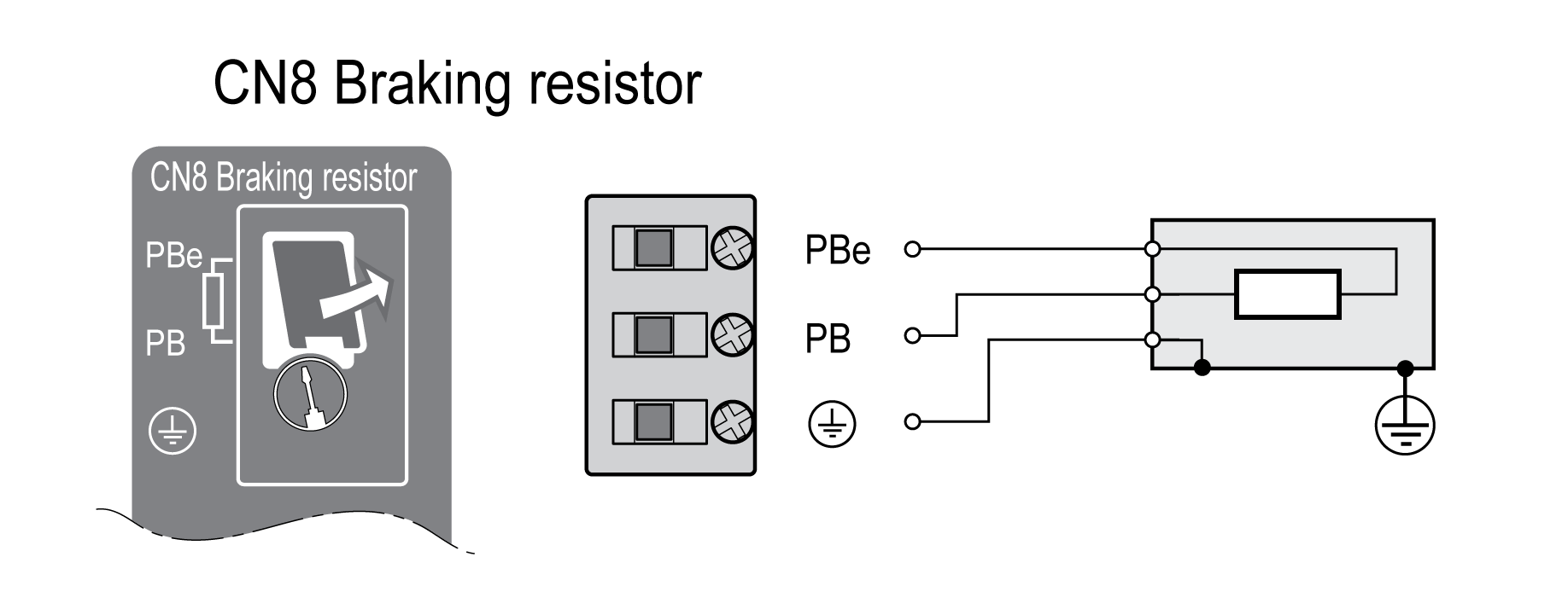
Connection Braking Resistor Cn8 Braking Resistor

Motor And Shunt Braking Resistor Hydra

Vw3a7753 Braking Resistor 16 Ohms 14 Kw Ip23 Schneider Electric Global
Shunt Braking Resistor Venus

Optional Devices Toshiba Inverter Tosvert Vf Series

China Rxlg And Rxhg Wirewound Variable Braking Resistor China Ac Drive Variable Frequency Drive
Http Www Deltronics Ru Images Manual Vfdb 4110 4160 4185 I En Pdf
Www Yaskawa Com Delegate Getattachment Documentid Pn Resistors 02 Cmd Documents Documentname Pn Resistors 02 Pdf
Library E Abb Com Public A0762b1e0ab1d2cdb4c Lvd Eotn12u En Pdf
Powerflex External Brake Resistor Electrician Talk
Q Tbn And9gctrpsaeqf 9yhmbxguhj0yxhrdeut6jaud0f6zhb9vmevha3avq Usqp Cau

Dynamic Braking Resistor For Vfd Dbr Connection Rating Selection Hindi Youtube

How To Use Braking Resistor With Atv930 Youtube

Dynamic Braking Resistor For Vfd Dbr Connection Rating Selection Hindi Youtube
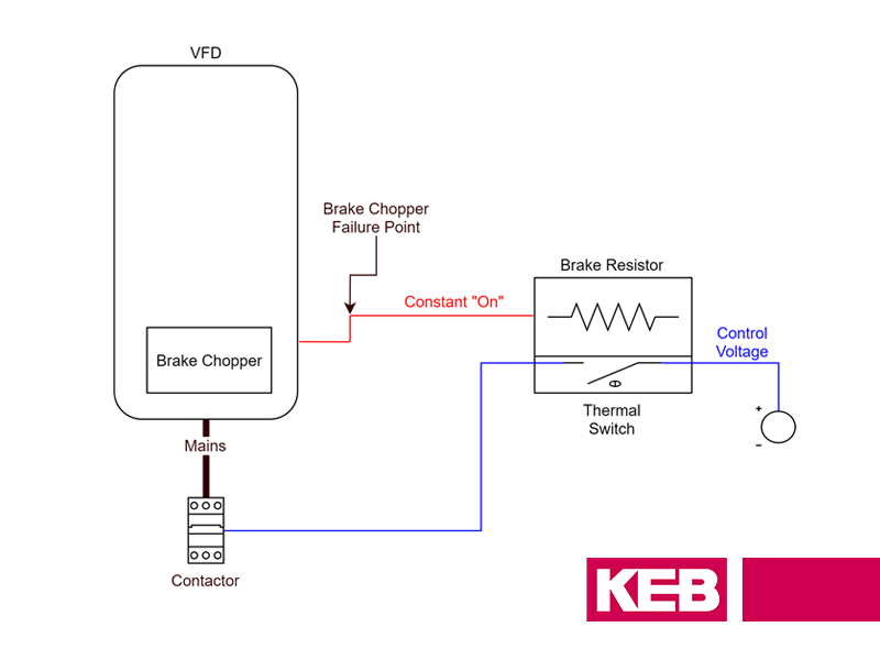
3 Ways To Protect A Vfd Braking Resistor From Short Circuit Failure Keb

Plant Engineering Regenerative Solutions

Beckhoff Information System English
Further Information Of Frequency Inverters Technical Guide For Frequency Inverters Omron Industrial Automation
Hubbellcdn Com Installationmanuals Powerohm Brakingmod Pw Pdf
Www Damencnc Com Userdata File Teknomotor Configmanual V2 Pdf

Types Of Braking In A Dc Motor Electrical4u
3 Ways To Protect A Vfd Braking Resistor From Short Circuit Failure Keb
I500 Brake Resistor Connection Long Version Megaresistors

5hp Huan Yang Vfd Swap To One With Braking Resistor Youtube
Hubbellcdn Com Installationmanuals Powerohm Brakingmod Lg 24v Pdf
Connection Diagram Of Electric Drive With An External Resistor A Download Scientific Diagram
Http Www Parker Com Literature Electromechanical north america Catalogs Brochures Space optimized parker vfd solutions for complex systems Pdf
3 Phase 380v 18kw To 560kw Big Power Motor Ac Drive
Source High Current Wirewound Braking Resistor On M Alibaba Com
Braking And Stopping Iknow Knowledge Base Invertek Drives Invertek Drives
Connection Equipment Toshiba International Corporation

Motor And Shunt Braking Resistor Triton
2
Dynamic Braking Resistors Fortress Resistors Design And Manufacturing

Acta Energetica Improvement Of Transient Stability By Means Of A Series Braking Resistor

Motor And Shunt Braking Resistor Triton

Optional Devices Toshiba Inverter Tosvert Vf Series

Dynamic Breaking With A Dc Motor Reversal Control

China High Power Braking Resistor 1000w 50 Ohm Resistor China Ac Drive Variable Frequency Drive

China Bellows Resistors Rxhg Wire Winding Resistor Braking Resistor China Ac Drive Variable Frequency Drive
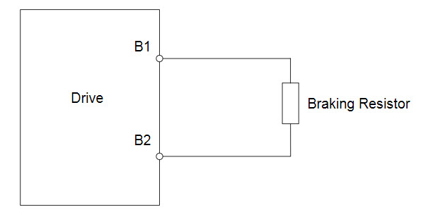
Connecting A Braking Resistor Or Cdbr Braking Unit To A Drive Smaller Models

Dynamic Braking Resistor Circuit
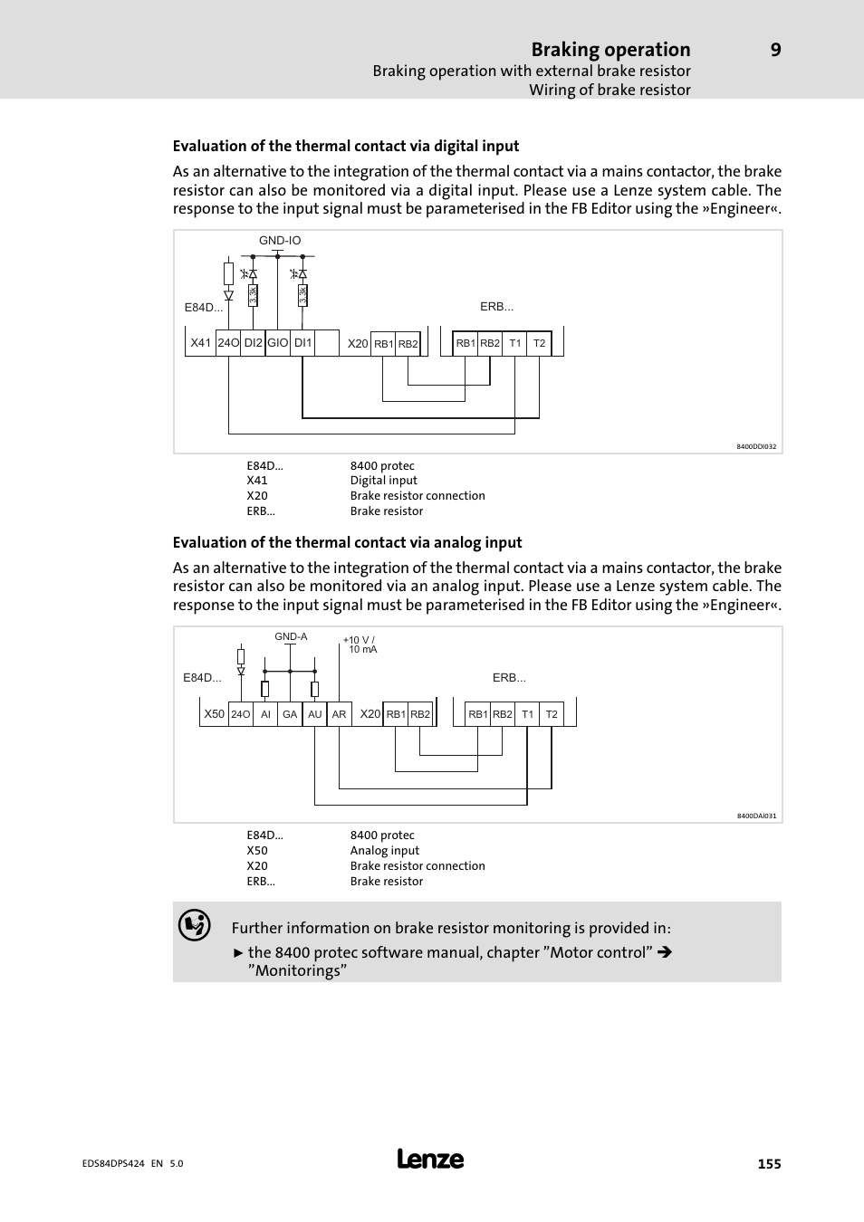
Braking Operation Lenze 8400 Protec Manual User Manual Page 155 198
Dynamic Braking Resistor Selection Calculation
Www Danotherm Com Download 18 445bfda2b713eaf A brake resistor perspective on cables Pdf
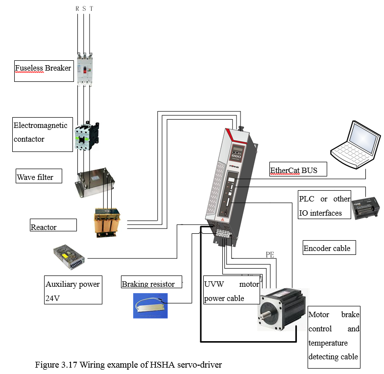
3 4 Interface Definitions And Wiring Of Driver
Faq What Is Dynamic Braking And When Is It Used
Http Files Danfoss Com Download Drives Doc Mg90o102 Pdf
Dynamic Braking Resistor Selection Calculation
When And How Should I Select A Braking Resistor Manufacturingtomorrow

Regenerative Braking On Motor Driven Axes Digikey

Dimensioning Of Ehv Series Braking Resistor For Large Thermal Generators Semantic Scholar
Www Yaskawa Com Delegate Getattachment Documentid Pn Resistors 02 Cmd Documents Documentname Pn Resistors 02 Pdf

Motor And Shunt Braking Resistor Titan

Dynamic Braking Resistor Filnor Resistors
Cache Industry Siemens Com Dl Files 7 Att 4144 V1 V70 Spindle Fsd 1ph1 7 5 Kw 6000rpm 11kw 8000rpm Tech Spec 0416 En Us Pdf


