Rf Sputtering
Radio frequency (RF) power can be used for sputter deposition of insulating target materials, and pulsed DC power can be used for reactive sputter deposition of insulating materials from a conductive metal target DC magnetron sputtering is available in a variety of source configurations and compatible with many of Angstrom’s process control capabilities and advanced fixturing options.
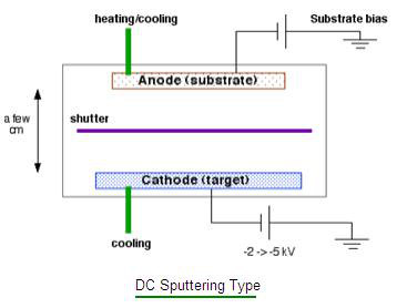
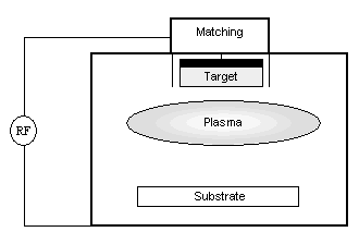
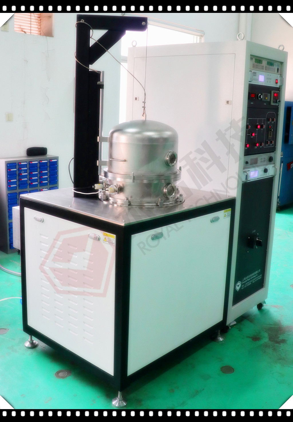
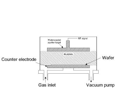
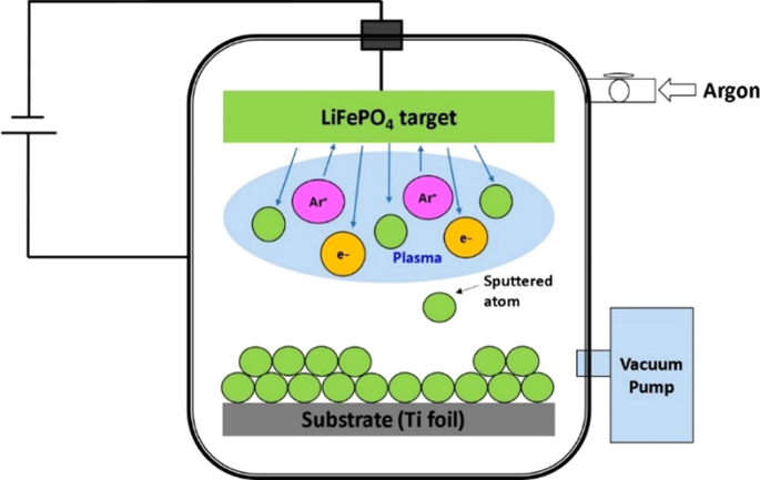
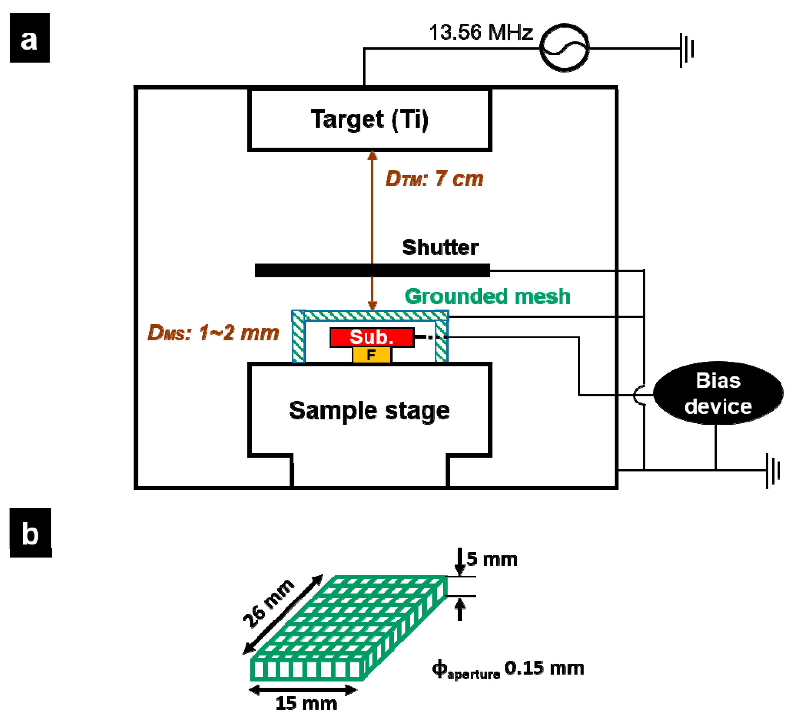
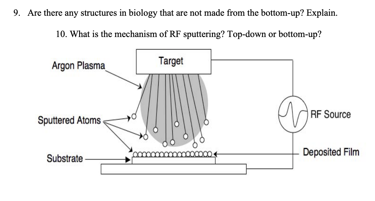
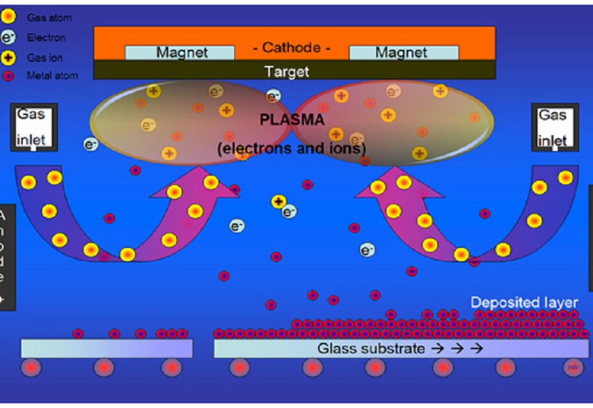
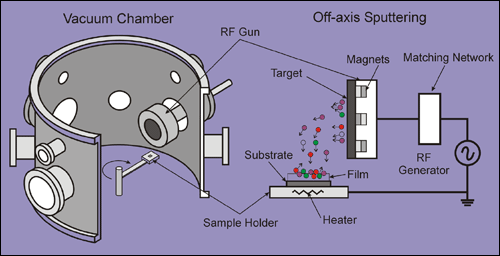
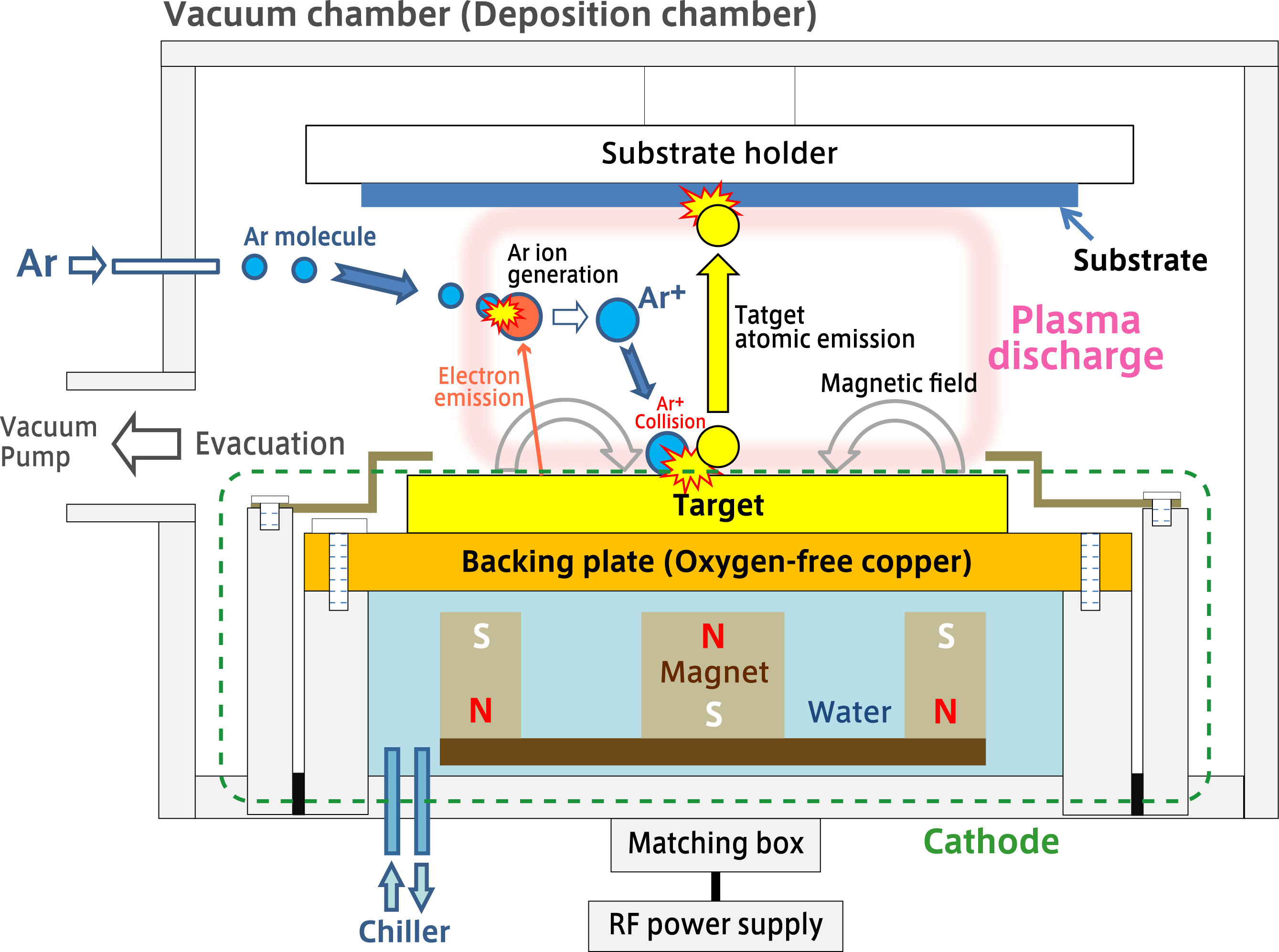
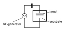
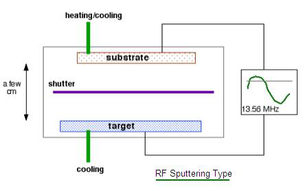
Rf sputtering. How Sputtering Works Magnetron Sputtering Download Technology Note TN 000 100 02/03 General Principle of Operation The above illustration describes a generic manifestation of a magnetron sputtering source DC, pulsed DC, AC and RF power supplies may be used, depending upon target material, if reactive sputtering is desired and other factors A permanent magnet structure is located behind a target serving as a deposition source. With the RF power supply, in RF Sputtering, the polarity of the electrical potential changes with each periodic cycle, result in discharging the electrical charges accumulated on the target surface Sputtering models DST1300 , DST3 , DST3T are equipped with RF power supply and impedance matching box and are able to do RF sputtering. RF magnetron sputtering is a technique where Argon ions are accelerated by a RF electric field to hit a target made of the material to sputter The target is sputtered in all directions, in particular, sputtered atoms will reach the substrate placed in front of the target, but outside of the plasma, to prevent etching by the plasma.
RF plasmas tend to fill the chamber as opposed to DC plasmas which are confined to the cathode • Normally both the target and substrate should sputter This can be overcome by making the target area small compared to the substrate • While any type of film can be RF sputtered, deposition rates are still low •. When a target is bombarded with fast heavy particles, erosion of the target material occurs The process, when occurring in the conditions of a gaseous glow discharge between an anode and cathode is termed sputtering Enhancement of this process for scanning electron microscopy (SEM) sample coating is obtained by the choice of a suitable ionization gas and target material. More about RF sputtering In its simplest representation, the phenomenon of sputtering consists of material erosion from a target on an atomic scale, and the formation of a thin layer of the extracted material on a suitable substrate The process is initiated in a glow discharge produced in a vacuum chamber under pressurecontrolled gas flow.
The development of magnetron sputtering deals with both of these issues simultaneously By using magnets behind the cathode to trap the free electrons in a magnetic field directly above the target surface, these electrons are not free to bombard the substrate to the same extent as with diode sputtering. RF sputtering imposes no restrictions on the layers which can be deposited, since nonconductive or semiconductive materials such as Si3N4, Al2O3, BN or TiB2 can also be sputtered From Comprehensive Hard Materials, 14. RF or Radio Frequency Sputtering is the technique involved in alternating the electrical potential of the current in the vacuum environment at radio frequencies to avoid a charge building up on certain types of sputtering target materials, which over time can stop the discharge of sputtering atoms terminating the sputtering process.
2) the ions sputter atoms from the target;. The CMS18 is an extremely flexible three target reactive sputtering system with a load lock capable of small parts through 6" wafers It has 2 RF sources and one DC source with pulse functions The system is capable of depositing multilayer film stacks, alloys, and reactively sputtered oxides and nitrides. RF sputtering uses alternate current (AC) power instead of DC power to form an AC sputtering system Since the frequency of commonly used AC power is in the RF range (5~30MHz), this sputtering method is called RF sputtering.
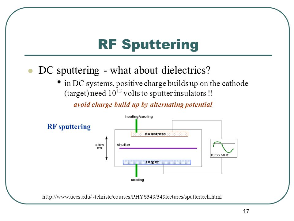
According to Material Science of thin Films by Milton Ohring, "RF sputtering essentially works because the target selfbiases to a negative potential Once this happens, it behaves like a DC target where positive ionbombardment sputters away atoms for subsequent deposition" So far so good. RF (Radio Frequency) Sputtering DC sputtering cannot be used for depositing dielectrics because insulating cathode will cause charge build up during Ar bombarding ¨reduce the voltage between electrodes ¨discharge distinguishes Substrate 1356 MHz eAr eAr t Target Target Sheath Substrate Sheath ~ Solution use AC power. 3) the sputtered atoms get transported to the substrate through a region of reduced pressure;.
The RF magnetron sputtering process is especially useful for making thin films out of materials that are nonconducting These materials may have more difficulty forming into a thin film because they become positively charged without the use of magnetism Atoms with a positive charge will slow down the sputtering process and can “poison” other particles of the target material, further slowing down the process. The highenergy particles used in sputterdeposition are generated by glow discharges A glow discharge is a selfsustaining type of plasma created by applying an RF field to a pressurized gas like argon, creating free electrons within the discharge region. Or why one should choose PLD over sputtering except depositing complicated oxides (eg super conductors or perovskites) It is well known that PLD can transfer the exact phase from the target to substrate, but thats what RF sputtering can also do for insulating target Basically PLD has been successful for growing epitaxial films.
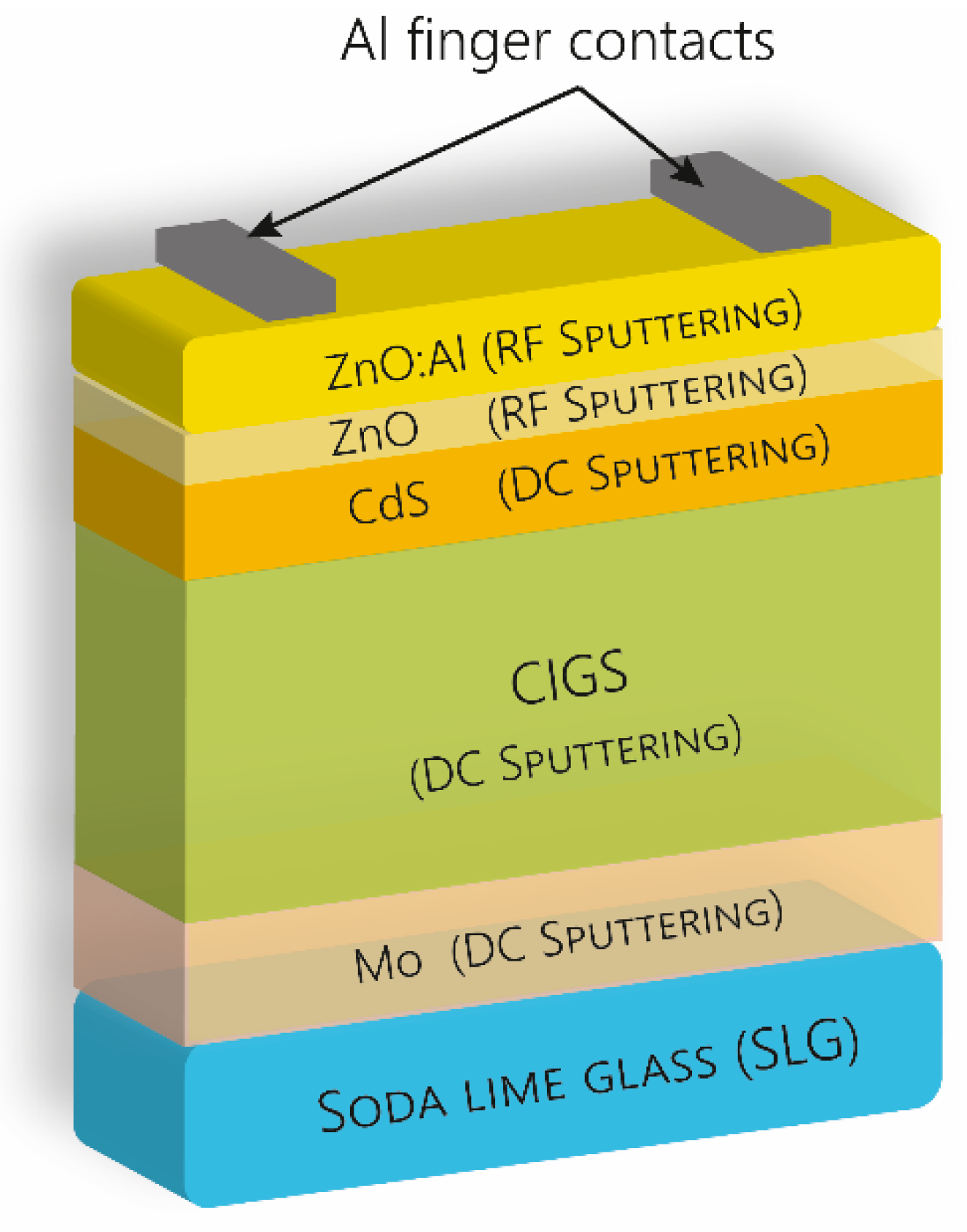
In this video I am discussing about the sputtering (DCRF) for thin film deposition. According to Material Science of thin Films by Milton Ohring, "RF sputtering essentially works because the target selfbiases to a negative potential Once this happens, it behaves like a DC target where positive ionbombardment sputters away atoms for subsequent deposition" So far so good. Laserdriven physical vapor deposition (LDPVD) and radiofrequency (rf) sputtering have been used to fabricate thinfilm solar cells on SnOsub 2coated glass substrates The laserablation process readily permits the use of several target materials in the same vacuum chamber and complete solar cell structures have been fabricated on SnOsub 2coated glass using LDPVD for the CdS, CdTe, and CdClsub 2.
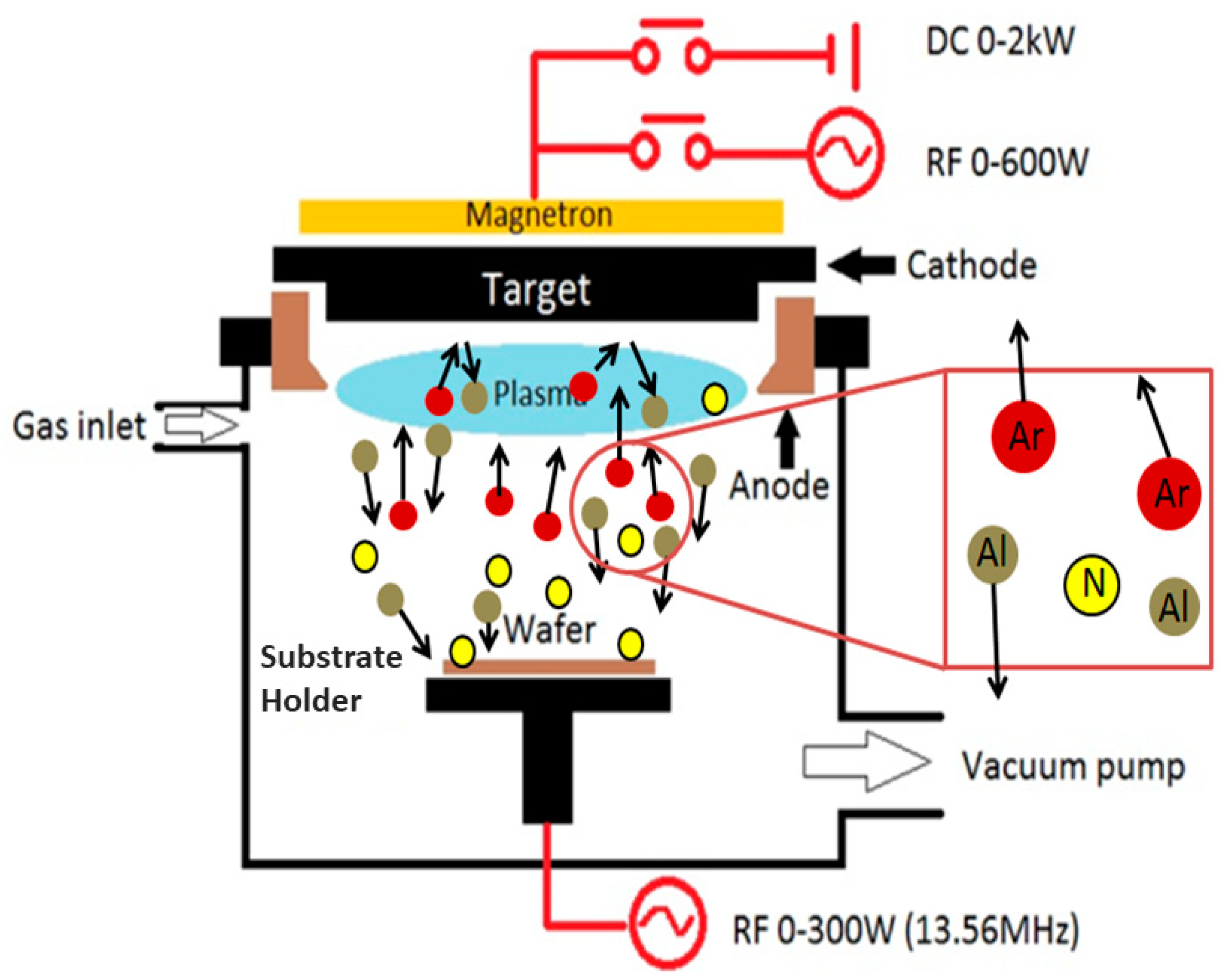
Sputtering only happens when the kinetic energy of the incoming particles is much higher than conventional thermal energies ( ≫ 1 eV ) When done with direct current (DC sputtering), voltages of 35 kV are used When done with alternating current ( RF sputtering), frequencies are around the 14MHz range. Add a reactive gas (oxygen, nitrogen) to the inert gas flow The reactive gas goes in to a chemical reaction with the sputtered atoms If the sputtering rate is faster than the chemical reaction rate, then the reaction will take place on the substrate Adjust gas flow to get good stochiometry (chemical composition). Sputtering is a versatile form of physical vapor deposition which can be used to deposit coatings of conductive or insulating materials It uses ionized gas to ablate (“sputter”) a target to create a thin film of that material on a substrate.
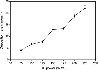
RF sputtering Advantages Following are the RF sputtering advantages It produces better film quality and step coverage compare to evaporation It helps in deposition of wide variety of insulators, metals, alloys, composites etc It Works well for insulating targets. What is RF Sputtering?. RF Sputtering can be used for the coating of dielectric or insulative materials that can take on a charge that results in arcing in the vacuum chamber with convention DC Sputtering However, RF Sputtering deposition rates are slower than DC Sputtering rates and have higher power costs and so is usually used on smaller substrates to be coated.
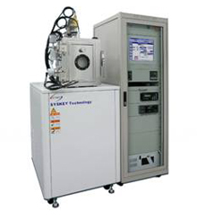
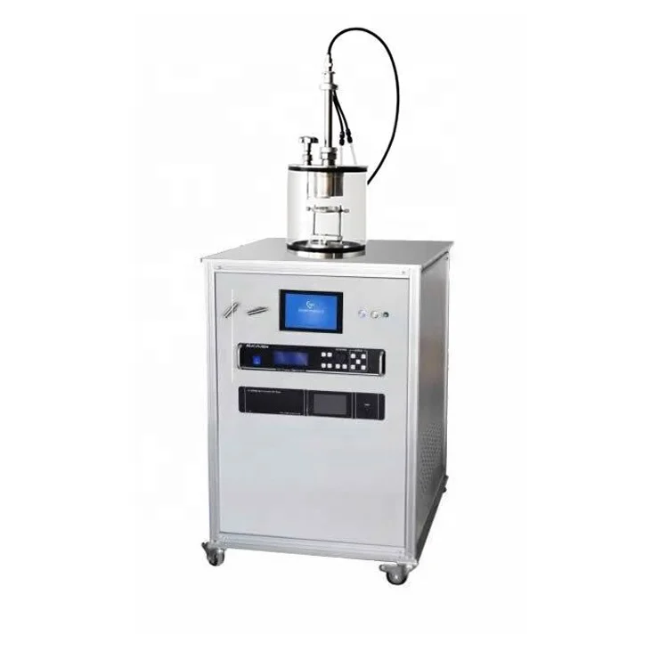
Reactive sputtering is a process that allows compounds to be deposited by introducing a reactive gas (typically oxygen or nitrogen) into the plasma which is typically formed by an inert gas such as argon (most common), xenon, or krypton In this process the reactive gas is “activated” by the plasma and chemically reacts with the target material which is subsequently deposited on the substrate. RF Generators and Matching Networks 100, 300, 600, 1000 and 00 Watt 1356 MHz RF generators for sputtering and RF biasing DC Generators750 W and 1500 W continuous DC generators with integral 4 way switchboxes Pulsed DC Generators 1000, 1500 and 5000 Watt asymmetric bipolar pulsed DC generators. Features of Euclid's RF sputtering system “Turmeric” mobile workstation on wheels 300 Watt CW RF input power UHV environment down to the low 1010 Torr level All stainless steel (from the gas cylinder regulator to the mass flow controller) UHP Argon supply system with purifier.
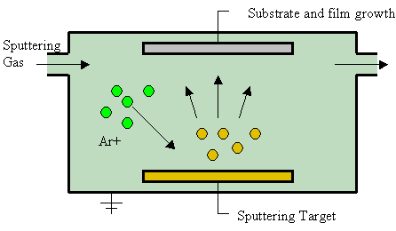
RF Bias sputtering Negative wafer bias enhances resputtering of film Varieties of sputtering experience Target Substrate Vplasma Ar Vbias ≈100 V Ar Some resputtering of wafer V≈1 kV Bias is one more handle for process control Used in SiO2 denser, fewer asperities Bias affects stress, resistivity, density,. Sputtering is a technique used to deposit thin films of a material onto a surface (aka "substrate") By first creating a gaseous plasma and then accelerating the ions from this plasma into some source material (aka "target"), the source material is eroded by the arriving ions via energy transfer and is ejected in the form of neutral particles either individual atoms, clusters of atoms or molecules. Comparison between TiO 2 deposited by RF magnetron sputtering at RT and without any intentional substrate bias Each of the deposition parameters has an influence on the energy of the deposition particles and we have to take into consideration the geometry of the deposition chamber as well.
In addition to the comments from the other researchers on the international agreement to reserve this frequency for industrial and laboratory processes, the RF signal is used in sputtering, since. RSeries RF generator packages provide reliable power for Magnetron Sputtering, Plasma Generation, & RF Biasing to meet your process requirements KJLC DC Series DC Sputtering & DC Bias The KJLC DC Series power supplies range in power levels from 1kW to 1kW KJLC®TruPlasma Pulsed DC Sputtering Power Supplies. And 4) the sputtered atoms condense on the substrate, forming a thin film.
Background on RF Sputtering System Physical sputtering is driven by momentum exchange between the ions and atoms in the materials, due to collisionsThe incident ions set off collision cascades in the target. Sputtering Applications Angstrom Sciences designs, engineers, and manufactures a complete line of magnetron sputtering cathodes for a variety of R&D and production applications The solid construction, patented magnetron technology and turbulent water flow designed into every one of our magnetrons provides our customers the superior performance. Sputtering is a technique, and when properly optimised, it can be upscaled to larger area substrates Simple oxide compounds like (SnO2, ZnO et) are rel;atively easy to optimize, whereas multicomponent oxides the optimization takes a little longer With this technique you can easily up scale for industrial applications.
Sputtering is a versatile form of physical vapor deposition which can be used to deposit coatings of conductive or insulating materials It uses ionized gas to ablate (“sputter”) a target to create a thin film of that material on a substrate. RFsputtering is a suitable technique to fabricate optical planar waveguides and photonic microcavities operating in the visible and NIR regions Sputtering techniques are widely used in industrial process because high quality films can be obtained at low temperature substrates. Therefore, any material can be sputterdeposited theoretically using RF magnetron sputtering But there is one thing in common for any type of magnetron sputtering the interaction between the magnetic field and the electric field causes the electrons to spiral in the vicinity of the target surface, thereby increasing the probability that electrons will strike the argon gas to generate ions.
More about RF sputtering In its simplest representation, the phenomenon of sputtering consists of material erosion from a target on an atomic scale, and the formation of a thin layer of the extracted material on a suitable substrate The process is initiated in a glow discharge produced in a vacuum chamber under pressurecontrolled gas flow Target erosion occurs due to energetic particle bombardment by either reactive or nonreactive ions produced in the discharge. In the present study, a practical technique of radio frequency (RF) sputtering was selected to incorporate W 6 species into TiO 2 lattice It was found that TiO 2 nanotubes sputtered at high energy of 50 W for 30 sec demonstrated a maximum photocurrent density of ~ 24 mA/cm 2 with photoconversion efficiency ~ 6 %. A general purpose sputtering system employing up to three 8″ diameter circular cathodes in DC magnetron, RF magnetron, or RF diode configurations Power options are available up to 2 kw RF and 5 kw DC PerkinElmer 4410 A delta target sputtering system designed for high rate deposition of metals and metal alloys.
The RFsputtered film will be smoother and have better packing density RF also deposits the film at about % of the DC rateIf you want to sputter using DC, pulsed DC, or AC, you must have a conductive (or semiconductive) target I always check the conductivity of a target by placing my ohm meter probes anywhere on the target surface. The RF sputtering process has some advantage in terms of sim ple lowcost deposition system, absence of toxic/pyrophoric gases from the process and the possibility of sequential deposition of different films in the same system. RF or Radio Frequency Sputtering is the technique involved in alternating the electrical potential of the current in the vacuum environment at radio frequencies to avoid a charge building up on certain types of sputtering target materials, which over time can result in arcing into the plasma that spews droplets creating quality control issues on the thin films – and can even lead to the complete cessation of the sputtering of atoms terminating the process.
When done with alternating current (RF sputtering), frequencies are around the 14MHz range Sputter cleaning Surfaces of solids can be cleaned from contaminants by using physical sputtering in a vacuum Sputter cleaning is often used in surface science, vacuum deposition and ion plating In 1955 Farnsworth, Schlier, George, and Burger reported using sputter cleaning in an ultrahighvacuum system to prepare ultraclean surfaces for lowenergy electrondiffraction (LEED) studies. Sputtering Systems PVD Products manufactures sputtering systems for depositing metal and dielectric thin films on substrates up to 300 mm in diameter An array of magnetron sputtering sources, using RF, DC, or pulsed DC power, are operated singly or in codeposition mode to produce a wide variety of film compositions Our magnetron sputtering sources range in size from 1 inch (25 mm) to 8 inches (0 mm) in diameter with options such as insitu tilt for fine adjustments of the deposition. • RF sputtering has a wider range of application and is suitable for all the materials for conductive and nonconductive materials, but it most commonly used for depositing of dielectric sputtering target materials • The deposition rate is lower compare with DC sputtering • It is used for smaller substrate sizes due to the high cost.
Sputtering is a technique used to deposit thin films of a material onto a surface (aka "substrate") By first creating a gaseous plasma and then accelerating the ions from this plasma into some source material (aka "target"), the source material is eroded by the arriving ions via energy transfer and is ejected in the form of neutral particles either individual atoms, clusters of atoms or molecules. RF Sputtering provides several advantages It works well with insulating targets The sign of the electrical field at every surface inside the plasma chamber is changing with the driving RF frequency This avoids chargeup effects and reduces arcing RF Diode sputtering technology, recently developed works even better, because it does not need magnetic confinement and provides optimum coating uniformity. Description The AJA UHV Orion dielectric sputter system is capable of reaching UHV pressures as low as 1E10 Torr It is equipped with a load lock that allows for automatic sample transfer There are eight magnetron guns, seven 2" guns, and one 3" gun A total of two RF and three DC power supplies can be used on any of the eight guns, some with an internal switch box allowing for one power source to be sequentially routed to different guns, enabling automatic processes without manual cable.
Sputter deposition, commonly called sputtering, removes atoms/molecules from a solid target's surface, projecting them into the gas phase from which they condense on another surface. While doing the RF magnetron sputtering some reflected power develops which needs to make null in order to get the plasma I am facing continuous rise of the reflected power within few minutes even. Comparison between TiO 2 deposited by RF magnetron sputtering at RT and without any intentional substrate bias Each of the deposition parameters has an influence on the energy of the deposition particles and we have to take into consideration the geometry of the deposition chamber as well.
I have finally been successful in creating a conductive, clear layer of indiumtin oxide on a microscope slide In this video, I show the process and explain. Radio frequency (RF) magnetron sputtering is also used as an alternative fabrication method for SiN The main motivation is to grow hydrogenfree lowtemperature SiN which is not possible with LPCVD and PECVD methods In the RF magnetron sputtering process of SiN a silicon target is ion bombarded by the elements from the N 2 and Ar source gases The energy of the bombarding ions can be controlled by the substrate RF bias. RF plasmas tend to fill the chamber as opposed to DC plasmas which are confined to the cathode • Normally both the target and substrate should sputter This can be overcome by making the target area small compared to the substrate • While any type of film can be RF sputtered, deposition rates are still low •.
Radio Frequency Sputtering RF sputtering imposes no restrictions on the layers which can be deposited, since nonconductive or semiconductive materials such as Si3N4, Al2O3, BN or TiB2 can also be sputtered From Comprehensive Hard Materials, 14 Related terms ZnO;. Sputtering as a deposition technique may be described as a sequence of these steps 1) ions are generated and directed at a target material;. RF Sputtering Sputter deposition of insulating materials cannot be done with DC power Materials such as oxides, nitrides, and ceramics have very large DC impedance and require prohibitively high voltages to ignite and maintain a plasma Luckily, the impedance of these materials changes with the frequency of the applied power.
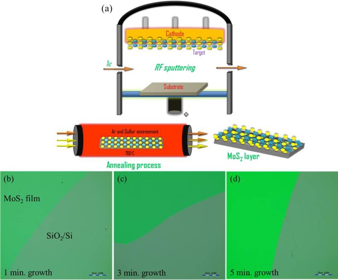
Radio frequency (RF) sputtering is a technique that is used to create thin films, such as those found in the computer and semiconductor industry Like direct current (DC) sputtering, this technique involves running an energetic wave through an inert gas to create positive ions. Sputtering Systems PVD Products manufactures sputtering systems for depositing metal and dielectric thin films on substrates up to 300 mm in diameter An array of magnetron sputtering sources, using RF, DC, or pulsed DC power, are operated singly or in codeposition mode to produce a wide variety of film compositions Our magnetron sputtering sources range in size from 1 inch (25 mm) to 8 inches (0 mm) in diameter with options such as insitu tilt for fine adjustments of the deposition. RF magnetron sputtering is a technique where Argon ions are accelerated by a RF electric field to hit a target made of the material to sputter The target is sputtered in all directions, in particular, sputtered atoms will reach the substrate placed in front of the target, but outside of the plasma, to prevent etching by the plasma.

Dr Shabbir A Bashar S Ph D Thesis Chapter 3 Section 2

Solved Hello In Rf Sputtering Deposotion Why We Designe Chegg Com

China Ti Target For Rf Sputtering Ti Target For Intermediate Frequency Ac Reactive Sputtering Ti Target For Non Equilibrium Magnetron Sputtering China Copper Custom Target Material
Rf Sputtering のギャラリー

Influence Of The Substrate Bias Voltage On The Crystallographic Structure And Surface Composition Of Ti6a14v Thin Films Deposited By Rf Magnetron Sputtering

Ppt Sputtering And Cvd Pvd Technology Powerpoint Presentation Free Download Id
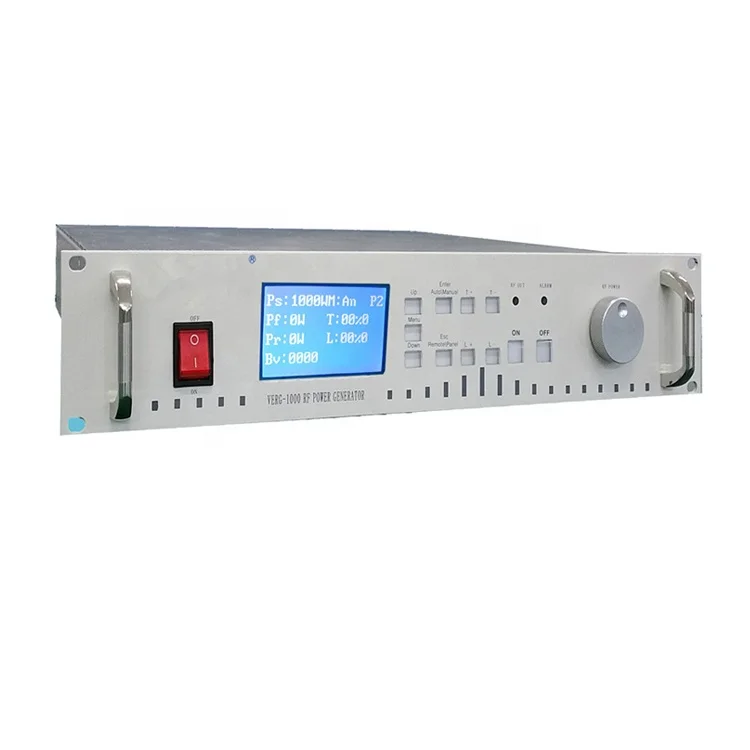
Compact 300w Rf Generator With Auto Matching Network For Diy Rf Sputtering Magnetron Sputtering Power Supply Buy Magnetron Sputtering Power Supply Product On Alibaba Com
Advances In Rf Sputtering Aultimut

Comparative Study On Spin On Coating And Rf Sputtering Ijesr
Www Osapublishing Org Oe Viewmedia Cfm Uri Oe 28 8 Seq 0
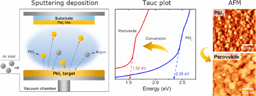
Lead Iodide Thin Films Via Rf Sputtering Crystal Growth Design X Mol
Portable Pvd Coating Machine Magnetron Sputtering Unit For Labrotary R D Dc Fm Rf Sputtering Lab Coater

Optimization Of Sputtering Parameters For The Deposition Of Low Resistivity Indium Tin Oxide Thin Films

Dc Sputtering Vs Rf Sputtering The Comparison Of Dc Sputtering And Rf Sputtering

Rf Magnetron Sputtering Laboratoire Charles Coulomb

Sputtering Configurations A Dc Sputtering B Rf Sputtering Download Scientific Diagram
Deposition Processes

Sputtering Processes For Thin Film Deposition Ppt Video Online Download

Magnetron Sputtering System Facility
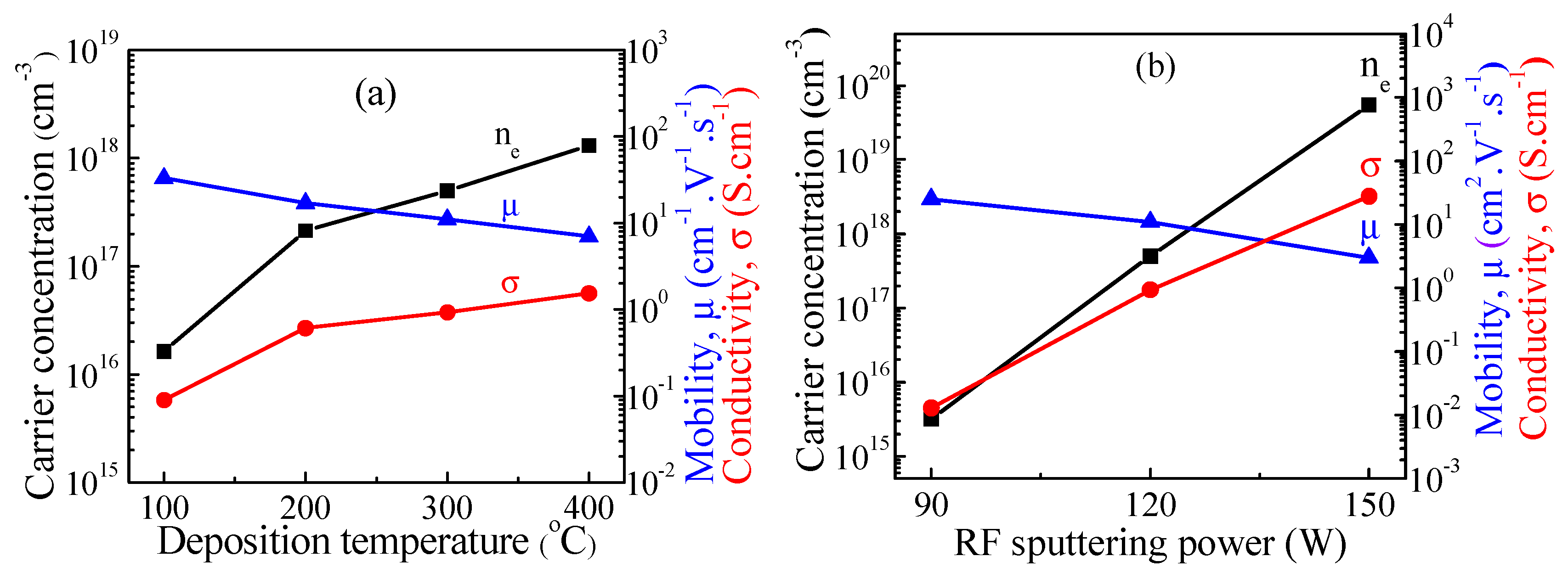
Influence Of Rf Power On Structural Morphology Electrical Composition And Optical Properties Of Al Doped Zno Films Deposited By Rf Magnetron Sputtering Springerlink
Electrochemistry Of Sputtered Hematite Photoanodes A Comparison Of Metallic Dc Versus Reactive Rf Sputtering Acs Omega X Mol
Sputtered Porous Li Fe P O Film Cathodes Prepared By Radio Frequency Sputtering For Li Ion Microbatteries Scientific Reports

In Rich Alxin1 Grown By Rf Sputtering On Sapphire From Closely Packed Columnar To High Surface Quality Compact Layers
Laboratory Dc And Rf Sputtering Coating Machine Dc Mf Sputtering Lab Coating Unit R D Lab Sputtering System
Coatings Free Full Text Generation Of Charged Ti Nanoparticles And Their Deposition Behavior With A Substrate Bias During Rf Magnetron Sputtering

Rf Sputtering Principles Ifn Trento
Rf Sputtering

Sputter Deposition An Overview Sciencedirect Topics

Characterization Of Sio2 And Tio2 Films Prepared Using Rf Magnetron Sputtering And Their Application To Anti Reflection Coating Sciencedirect
Q Tbn And9gcq6ynaxn 7xv2bpv6zz0biqcivqdlbjh2a0yv0djafxfqfnv76i Usqp Cau

Pin On Sputtering Targets

Rf Magnetron Sputtering System At Rs Piece Sputtering Systems Id

Pdf Stress Evaluation Of Rf Sputtered Silicon Dioxide Films For Mems Semantic Scholar
Core Ac Uk Download Pdf Pdf
Sputter Deposition Wikipedia

China 1 Magnetron Sputtering Source With Flexible Head For Diy Rf Dc Sputtering Coater China Magnetron Sputtering Source Magnetron Sputtering Cathode

Faq Vaccoat
Scientific Analytical Instruments Rf Dc Sputtering System
Q Tbn And9gcqrrma6pky5 U7sohjkjyiiokgbcikxhutol4ab7etg5jamztgg Usqp Cau
Solved 9 Are There Any Structures In Biology That Are No Chegg Com

In Rf Sputtering There Are Typically A Small Area Cathode Target And Download Scientific Diagram
Rf Magnetron Sputtering Ppt
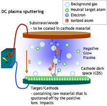
Scientific Analytical Instruments Rf Dc Sputtering System
Q Tbn And9gcsmv5sez6h2h0cqzl7jqe7m54c0p2spndvowf Wnheskv3v Wsg Usqp Cau

Edwards Auto 500 Turbo Three Target Rf Sputtering System Thin Film Deposition Semistar

Impact Of Plasma Electron Flux On Plasma Damage Free Sputtering Of Ultrathin Tin Doped Indium Oxide Contact Layer On P Gan For Ingan Gan Light Emitting Diodes Son 18 Advanced Science Wiley Online

Temperature Effects On Vo2 Thin Films Deposited By Rf Sputtering For The Degradation By Photocatalysis Of Methylene Blue And Naproxen In International Journal Of Chemical Reactor Engineering Volume 18 Issue 7

What Is Rf Sputtering With Picture

Hybrid Pvd Coater In Glove Box 2 Rf Sputtering 2 Evaporation Source Vtc H3 Gb

Rf Sputtering Principles Ifn Trento

3 Heads Compact 1 Rf Plasma Magnetron Sputtering Coater With Dc Magnetron Sputtering Option Vtc 3rf
Http Www Sfu Ca Gchapman E495 E495l9l Pdf

Figure 39 3 Schematic Of Rf Sputtering Chamber

Sputtering System Rf And Dc Sputtering Unit Importer From Bengaluru

Clipboard No 1 May 10
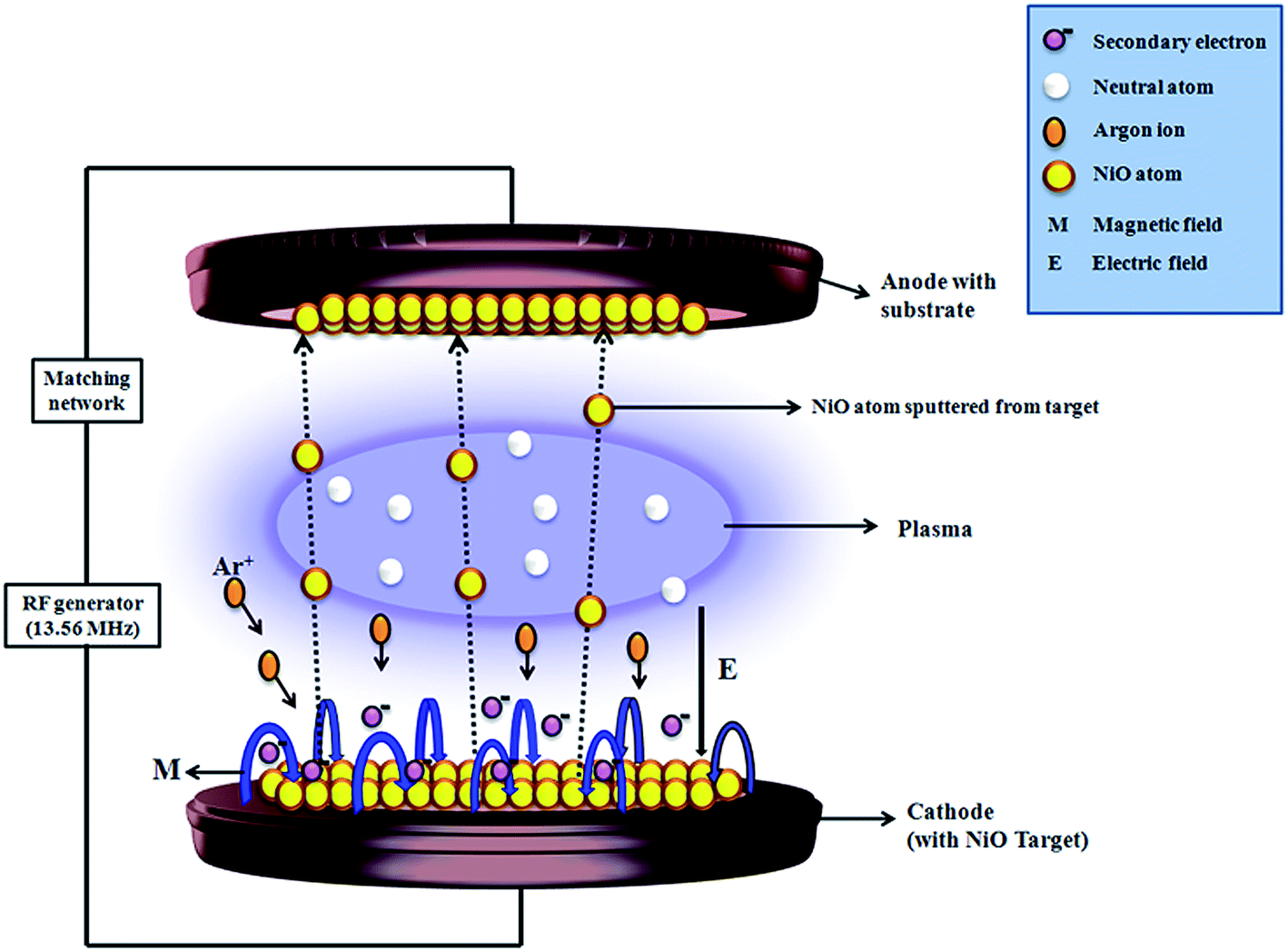
Improved Electrochromic Performance Of A Radio Frequency Magnetron Sputtered Nio Thin Film With High Optical Switching Speed Rsc Advances Rsc Publishing Doi 10 1039 C5rae

Rf Sputtering Of Polycrystalline 100 002 And 101 Oriented Aln On An Epitaxial 3c Sic 100 On Si 100 Substrate Journal Of Vacuum Science Technology B Vol 32 No 6
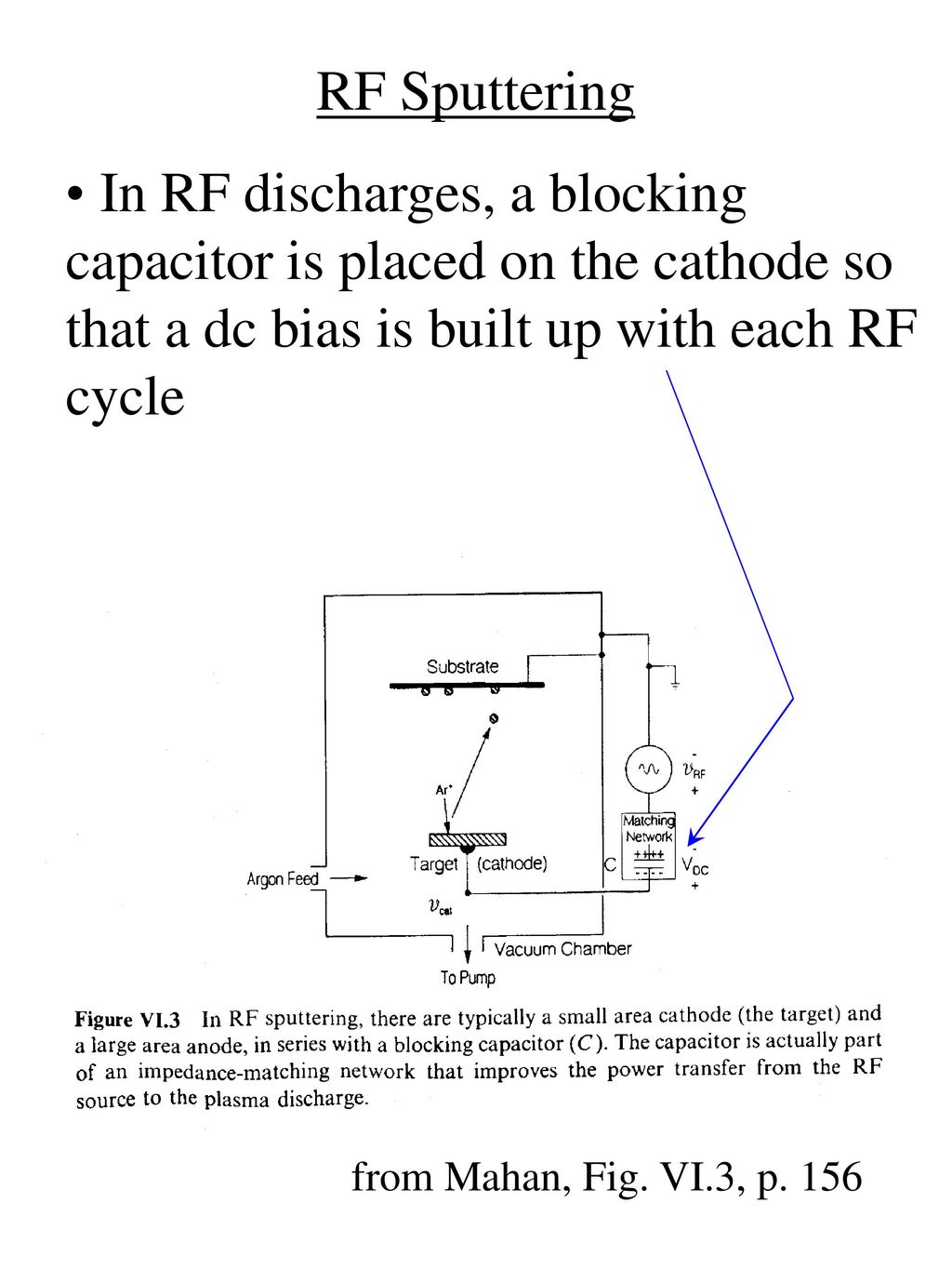
Dc Sputtering Disadvantage 1 Low Secondary Electron Yield Ppt Download

A Schematic Diagram Of The Radiofrequency Rf Sputtering System For Download Scientific Diagram

Rf Sputtering Applications Ifn Trento

Rf Sputtering Three Pole Sputtering And Magnetron Sputtering Techniques Coating Club

1 Schematic Drawing Of A Rf Sputtering System Adapted From 92 Download Scientific Diagram
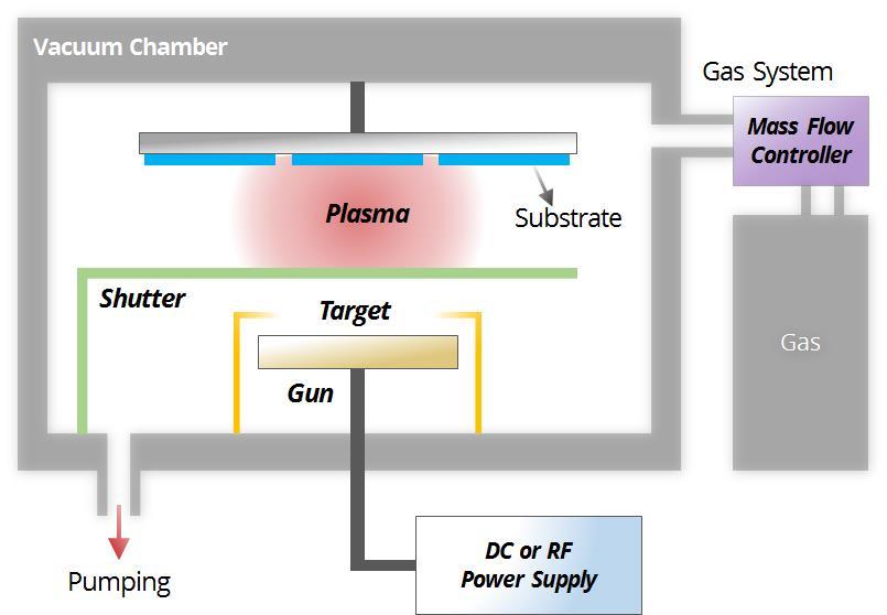
Technical Research Centre Trc

Faq Vaccoat

What Is Rf Sputtering
5 Sputter Coating Methods That Prepare Good Quality Film
Effect Of Al 2 O 3 Coatings Prepared By Rf Sputtering On Polyethylene Separators For High Power Lithium Ion Batteries Springerlink

Pvd Rf Sputtering Coating Principle Magnetron Sputter Deposition Process Animation Youtube
Process For Rf Sputtering Of Cadmium Telluride Photovoltaic Cell University Of Toledo Digital Repository
4 0 Thin Film Deposition Growth And Study Of Magnetostrictive Fesibc Thin Films For Device Applications

Pzt Thin Films Deposited By Rf Magnetron Sputtering Scientific Net

What Is Dc Sputtering
Effects Of Temperature And Deposition Time On The Rf Sputtered Cdte Films Preparation

Bol Com Peliculas Nanocristalinas De Gaas Crecidas Por Rf Sputtering Gordillo Delgado

What Is Rf Sputtering

Radio Frequency Sputtering An Overview Sciencedirect Topics

Research Center For Magnetic And Spintronic Materials

Sputtering Thin Film Deposition Euclid Techlabs

Schematic Of The Ito Rf Sputtering System Download Scientific Diagram

Rf Sputtering Applications Ifn Trento

Objectives Template
More About Rf Sputtering

High Rate Sputtering Deposition Of Silicon Oxide Thin Films From New Sio2 Si Target Composition Journal Of Vacuum Science Technology A Vol 27 No 4
Layer Modulated Wafer Scale And Continuous Ultra Thin Ws2 Films Grown By Rf Sputtering Via Post Deposition Annealing Journal Of Materials Chemistry C Rsc Publishing
Sensors Free Full Text Reactive Sputtering Of Aluminum Nitride 002 Thin Films For Piezoelectric Applications A Review Html

Figure 1 Align Ag Nanorods Via Oxidation Reduction Growth Using Rf Sputtering
Lab Dc Rf Magnetron Sputtering Equipment System View Rf Sputtering Sputter System Cyky Product Details From Zhengzhou Cy Scientific Instrument Co Ltd On Alibaba Com

Iran Nanoelectronic Center Equipments
Ssp1000 Suga Co Ltd
Coatings Free Full Text Rf Dc Magnetron Sputtering Deposition Of Thin Layers For Solar Cell Fabrication Html

Cdznte Thin Films Growth By Rf Sputtering For Cdte Solar Cells Semantic Scholar

Difference Between Rf Sputtering And Dc Sputtering Rf Sputtering Vs Dc Sputtering
Large Area Continuous And High Electrical Performances Of Bilayer To Few Layers Mos 2 Fabricated By Rf Sputtering Via Post Deposition Annealing Method Scientific Reports
Q Tbn And9gcrs4t5gdkz1ormcnktha6w4d Cb6uby8bir Jwcoybrpe Zmzh8 Usqp Cau

Rf Sputtering Principles Ifn Trento
Research Facilities

Rf Sputtering Applications Ifn Trento

Rf Sputtering Principles Ifn Trento
Advances In Rf Sputtering Aultimut
Coatings Free Full Text The Effect Of Rf Sputtering Conditions On The Physical Characteristics Of Deposited Gegan Thin Film

Top Pdf Rf Sputtering 1library

Development Of Rf Magnetron Sputtering Method To Fabricate Pzt Thin Film Actuator Sciencedirect
Dc Sputtering Vs Rf Sputtering The Comparison Of Dc Sputtering And Rf Sputtering

Deposition Of Tantalum Thin Films By Rf Sputtering With Substrate Bias

1 Schematic Diagram Of Radio Frequency Rf Sputtering System From Download Scientific Diagram


