Solenoid Switch Diagram
Fuel Shutoff Solenoid, Mag Switch, Starter Wiring What We Do Seaboard Marine delivers “Guaranteed Better Than Factory” Performance, Parts, Design, and Engineering for Cummins and other Marine Diesel applications.
Solenoid switch diagram. The switch lets you drain one battery, then switch to another to start the engine You must then switch to “both” in order to charge both batteries or have a separate diodetype battery isolator Pros No need to separate starter/ignition wiring from accessory wiring Cons Requires user to manually switch between batteries Heavy battery. Agriline Diesel Massey Ferguson 35 Wiring Diagram Diesel 3 Cylinder with dynamo (Generator) D E A F 4 Starter Solenoid 3 Glow Plug E Earth ( To tractor chassis) A Armature (No 1 on ignition switch) F Field (Small terminal on dynamo) 4mm wire 25mm wire 4mm wire 25mm wire 25mm wire 674 96AH battery Insulate wires with a good. There are pressure control solenoids, shift solenoids that direct fluid pressure to the appropriate clutches or bands, and a solenoid that directs fluid pressure to engage the TCC A solenoid contains a coil of wire with an iron plunger inside When current is applied to the solenoid it becomes an electromagnet and the plunger changes position.
The Starter Solenoid in your Mustang takes current from the battery and uses it to start your engine when you turn the key However, in Mustangs, it is prone to failure, so you may need to replace your Starter Solenoid at some point If this is the case with your Mustang and Starter Solenoid, order your new parts and install. Wiring a Solenoid Switch Machine for Remote Turnout Control Many model railroaders use the Atlas solenoid switch machines for remote turnout control They are relatively inexpensive, easy to hook up following the directions on the package, and they are readily available in most local hobby shops. Solenoid control valves that change valve position Open/Close etc by direct movment from a solenoid are called Direct Acting Solenoid control valves that change position Open/Close etc by opening small pilot circuits allowing pressurised air, fluid or gas to move the valve are called pilot operated or servo pressure assisted valves.
Warn Winch Wiring Diagram Solenoid At To Beautiful With At – Warn Winch Wiring Diagram Solenoid Wiring diagram also offers beneficial suggestions for tasks that might require some extra tools This guide even includes suggestions for added supplies that you might require as a way to end your assignments. BRAND NEW SOLENOID RELAY SWITCH FOR GOLF CART, MARINE, WINCH, & HEAVY DUTY This solenoid is used on Superwinch and many other winch and hydraulic applications It is a continuous duty solenoid and is guaranteed to perform equal or better than the solenoid it is replacing CONTINUOUSDUTY SWITCH 12VOLT 3TERMINAL FLAT BRACKET GROUNDED BASE. The rotary solenoid is an electromechanical device used to rotate a ratcheting mechanism when power is applied These were used in the 1950s for rotary snapswitch automation in electromechanical controls Repeated actuation of the rotary solenoid advances the snapswitch forward one position.
12 volt solenoid switches are ideal for 12 volt vehicle starters, winches, snow plows or other heavy electric motors This Insulated continuous 12 volt solenoid allows for a low input while generating a larger output Free shipping over $99!. Description Bombastic Structure Work Hard Complicated Case Warn Winch Solenoid regarding Warn Atv Winch Solenoid Wiring Diagram, image size 1024 X 750 px, and to view image details please click the image Here is a picture gallery about warn atv winch solenoid wiring diagram complete with the description of the image, please find the image you need. Lucas Starter solenoid Wiring Diagram– wiring diagram is a simplified normal pictorial representation of an electrical circuitIt shows the components of the circuit as simplified shapes, and the gift and signal associates along with the devices.
4 Pole Starter solenoid Wiring Diagram Collections Of Wiring Diagram for Phase Failure Relay New Starter Relay Wiring Wiring Diagram Starter solenoid Refrence Elegant 4 Pole solenoid 4 Pole solenoid Wiring Diagram Download Wiring Diagram Relay Starter Motor Fresh Ignition Relay Wiring. 12 volt solenoid switches are ideal for 12 volt vehicle starters, winches, snow plows or other heavy electric motors This Insulated continuous 12 volt solenoid allows for a low input while generating a larger output Free shipping over $99!. The switch lets you drain one battery, then switch to another to start the engine You must then switch to “both” in order to charge both batteries or have a separate diodetype battery isolator Pros No need to separate starter/ignition wiring from accessory wiring Cons Requires user to manually switch between batteries Heavy battery.
Use our part lists, interactive diagrams, accessories and expert repair advice to make your repairs easy. Reversing Solenoid Wiring Diagram Wiring Library – 12 Volt Winch Solenoid Wiring Diagram Wiring Diagram consists of numerous comprehensive illustrations that present the link of various products It consists of instructions and diagrams for different kinds of wiring strategies and other things like lights, windows, etc. To transbrake switch or transbrake solenoid terminal on delay box blue red yellow *for factory ignitions this wire connects to coil () negative shifnoid wiring diagram shifnoid ncrpm3000 rpm switch with delay c shifnoid ltd, 11 shifnoid rpmswitch w/delay r 12v 12v 12v 12v 87 87 87 85 85 85 30 30 30 86 86 86 shifnoid interface.
Need to fix your 17AF2ACP011 (08) Mustang RZT 50 Lawn Tractor?. Yes No Score 4 Cancel Add a comment. Or you are a student, or maybe even you who just want to know about Briggs And Stratton Solenoid Wiring Diagram Starter Solenoid Wiring Diagram For Lawn Mower – – – Concerbiz, size 800 x 600 px, source concerbiz Whatever you are, we attempt to bring the content that matches just what you are looking for You may come from an online.
Solenoid control valves that change valve position Open/Close etc by direct movment from a solenoid are called Direct Acting Solenoid control valves that change position Open/Close etc by opening small pilot circuits allowing pressurised air, fluid or gas to move the valve are called pilot operated or servo pressure assisted valves. Wire diagram ford starter solenoid relay switch Normally it is connected to the frame or to the batterys negative terminal One can find a range of reports tips content articles from any location in just secs Its essentially a big relay which provides power from the battery to the starter motor when the ignition key is turned over starting. Figure 56Solenoid switch diagram condition, the discharge current must be balanced by a charging current supplied from an external source, such Control Circuitry as a batterycharging alternator If the discharge current The solenoid shown in figures 55 and 56 is used.
Solenoid switches are used to control large current circuits with a low current switch These devices contain a high current switch which is controlled by a a magnetic actuator called a solenoid When a small current flows through the solenoid, the solenoid core will move, forcing the high current switch to the closed. Solenoid control valves that change valve position Open/Close etc by direct movment from a solenoid are called Direct Acting Solenoid control valves that change position Open/Close etc by opening small pilot circuits allowing pressurised air, fluid or gas to move the valve are called pilot operated or servo pressure assisted valves. Figure 56Solenoid switch diagram condition, the discharge current must be balanced by a charging current supplied from an external source, such Control Circuitry as a batterycharging alternator If the discharge current The solenoid shown in figures 55 and 56 is used.
Description How To Wire A Solenoid Switch Solenoid Wiring • Apointco with regard to Solenoid Switch Wiring Diagram, image size 800 X 349 px, and to view image details please click the image Here is a picture gallery about solenoid switch wiring diagram complete with the description of the image, please find the image you need. Description Bombastic Structure Work Hard Complicated Case Warn Winch Solenoid regarding Warn Atv Winch Solenoid Wiring Diagram, image size 1024 X 750 px, and to view image details please click the image Here is a picture gallery about warn atv winch solenoid wiring diagram complete with the description of the image, please find the image you need. How to start a car with a bad solenoid.
Below we've provided some Cub Cadet Wiring Schematics for our most popular models of Cub Cadet lawn care equipment These schematics are for reference purposes only when you are ready to purchase a specific part, please type that number into the search box above. Re Wiring switch to starter solenoid etc Return that key switch and get one for magneto ignition It will have w "M" posts on it That is where the 2 black wires from the points go to The black heavy gauge from the battery negative goes to a good ground on the powerhead, usually a mounting bolt for the starter. Switch wires switch wires to starter solenoid to starter solenoid shifnoid ltd, 16 10 gauge wire 10 gauge wire solenoid wire to relay solenoid wire to relay solenoid wire to ground (shifnoid or msd) use this diagram if your rpm switch or timer supplies "normally open 12v positive" (dedenbear or digital delay) use this diagram from.
Kubota B Parts Catalogs & Information Extensive diagrams and resources for Kubota equipment My machine shuts off and I hear clicking?. Briggs and Stratton Starter solenoid Wiring Diagram– wiring diagram is a simplified good enough pictorial representation of an electrical circuitIt shows the components of the circuit as simplified shapes, and the skill and signal contacts with the devices. How to start a car with a bad solenoid.
6 Connect the battery Ground cable to the Ground terminal of the DC Motor (diagram A3) 7 Connect the Positive cable from the battery to the start solenoid (diagram ) (See Battery Cable Gauge table for proper gauge for your length of cables) 8 Holding the bottom nut with a wrench, torque the battery connections to 3 lbft 9. Ford Starter Solenoid Wiring Diagram With Basic Images 2587 With, size 800 x 600 px, source saleexpertme Below are several of the leading drawings we receive from numerous resources, we hope these images will certainly serve to you, and with any luck extremely relevant to just what you want concerning the Ford F 150 Starter Solenoid Wiring Diagram is. The solenoids also rely on an electrical signal provided by other TCS system switches/senders via an electrical connection on the back or side of the solenoid (the Engine Harness or TCS Harness plugs into this connection).
Toro wiring diagram lawn mower solenoid related problems I need a Toro z master wiring schematic try toros web site you should be able to type in Disconnect battery from charger, wire harness, When the engine of a riding mower will not turn over, there are a few runs from the solenoid to the starter. The solenoids also rely on an electrical signal provided by other TCS system switches/senders via an electrical connection on the back or side of the solenoid (the Engine Harness or TCS Harness plugs into this connection). Ground activated switches are a bit different in that the switch coil is internally connected to the BAT post This means one end of the coil is always powered and the other end is connected internally to the solenoid switch post When a ground signal is given to the switch post, the current can flow through the coil, pulling in the contact.
Please check fuses, check relays, check fuel shut off solenoid, wiring connections and your key switch answered by anonymous on 10/30/ Q Oct 16, · How to test Solenoid / Injection Pump Fuel Cut Off FixitSam. Figure 56Solenoid switch diagram condition, the discharge current must be balanced by a charging current supplied from an external source, such Control Circuitry as a batterycharging alternator If the discharge current The solenoid shown in figures 55 and 56 is used. The switch lets you drain one battery, then switch to another to start the engine You must then switch to “both” in order to charge both batteries or have a separate diodetype battery isolator Pros No need to separate starter/ignition wiring from accessory wiring Cons Requires user to manually switch between batteries Heavy battery.
Power Flow Logic Diagram – Forward 2nd Speed. Micro Switch Testing The micro switches are simple 2 wire on/off switches You can test function with a voltmeter if you first verify 36v in on the supply Slowly depress accelerator pedal until the solenoid engages 36 volt electric club car wiring diagram with Solid State controller roady nimda Golf cart electrical. The solenoid draws a continuous current of 700mA when energised and a peak of nearly 12A so we have to consider these things while designing the driver circuit for this particular Solenoid valve Circuit Diagram The complete circuit diagram for Solenoid driver circuit is shown in the image below We will understand why it is designed so, once.
The solenoid switch is composed of a solenoid, which is an electromagnetic device that produces the attraction or retention of the moving core Most of the starter solenoid is fixed directly to the top of the starter 3Starter Relay The starter relay is another switch that is used to control the starting circuit. Please check fuses, check relays, check fuel shut off solenoid, wiring connections and your key switch answered by anonymous on 10/30/ Q Oct 16, · How to test Solenoid / Injection Pump Fuel Cut Off FixitSam. The solenoid was not engaging to release fuel to start the tractor I tested all 3 switches and they checked OK I purchased a new solenoid and it has worked for about 2 weeks Now it is doing the same thing again The motor will turn over when the 3 switches are engaged, but not the solenoid I checked all fuses and they are fine.
For example, if you don't know the specific system in which the ignition switch is located, look up ignition switch in the wiring diagram component location tables and go to the appropriate wiring diagram(s) which contain either full or partial views of the ignition switch Boost Control Solenoid Engine Performance Boost Sensor Engine. Brake Switch Wiring Diagram 139 Solenoid & Range Pressure Switch Wiring Diagram 140 Transmission System Wiring Diagram 141 Special Tools Listing 142 Solenoid Resistance Chart 146 Shift Solenoid Status Chart 146 Transmission Input/Output Ratio Table 147 Range. Starter solenoid wiring diagram from battery to solenoid Craftsman Riding Mower model i need to know how the wiring diagram from battery to solenoid to starter is configured Answer this question I have this problem too Subscribed to new answers Is this a good question?.
I need the wiring diagram for a Mercruiser Pre Alpha Tilt/Trim lift Pump, I am not sure it is wired correctly changed by the previous owner so the wires may not be correct but have voltage to the switch, it is a three wire motor, The 2 small terminals on solenoid one blue wire from the switch. Collection of 12 volt winch solenoid wiring diagram A wiring diagram is a streamlined standard pictorial depiction of an electrical circuit It shows the parts of the circuit as simplified forms, as well as the power and signal links between the devices. A starter solenoid is a switch that controls a high amp load with a low amp A couple tricks so you can install the direct fit solenoid on you polaris But a wiring diagram probably isnt going to include a picture of the starter solenoid mounted to where ever it is supposed to mount.
Ground activated switches are a bit different in that the switch coil is internally connected to the BAT post This means one end of the coil is always powered and the other end is connected internally to the solenoid switch post When a ground signal is given to the switch post, the current can flow through the coil, pulling in the contact. I need the wiring diagram for a Mercruiser Pre Alpha Tilt/Trim lift Pump, I am not sure it is wired correctly changed by the previous owner so the wires may not be correct but have voltage to the switch, it is a three wire motor, The 2 small terminals on solenoid one blue wire from the switch. The solenoids also rely on an electrical signal provided by other TCS system switches/senders via an electrical connection on the back or side of the solenoid (the Engine Harness or TCS Harness plugs into this connection).
3 Differences Between Starter Solenoid Switch & Starter Relay Many people think a starter solenoid switch and a starter relay to be the same, which is not true (Even wiki claim they are the same thing in the different name) They are way different in terms of their construction, working, and functions.
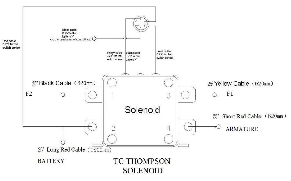
Dna Knowledge Base Tg Thompson Solenoid Wiring Diagram

Starter Solenoid The Definitive Guide To Solve All The Solenoid Problems

Diagram Superwinch Solenoid Switch Wiring Diagram Full Version Hd Quality Wiring Diagram Diagramoftruth Giornatedellaserra It
Solenoid Switch Diagram のギャラリー
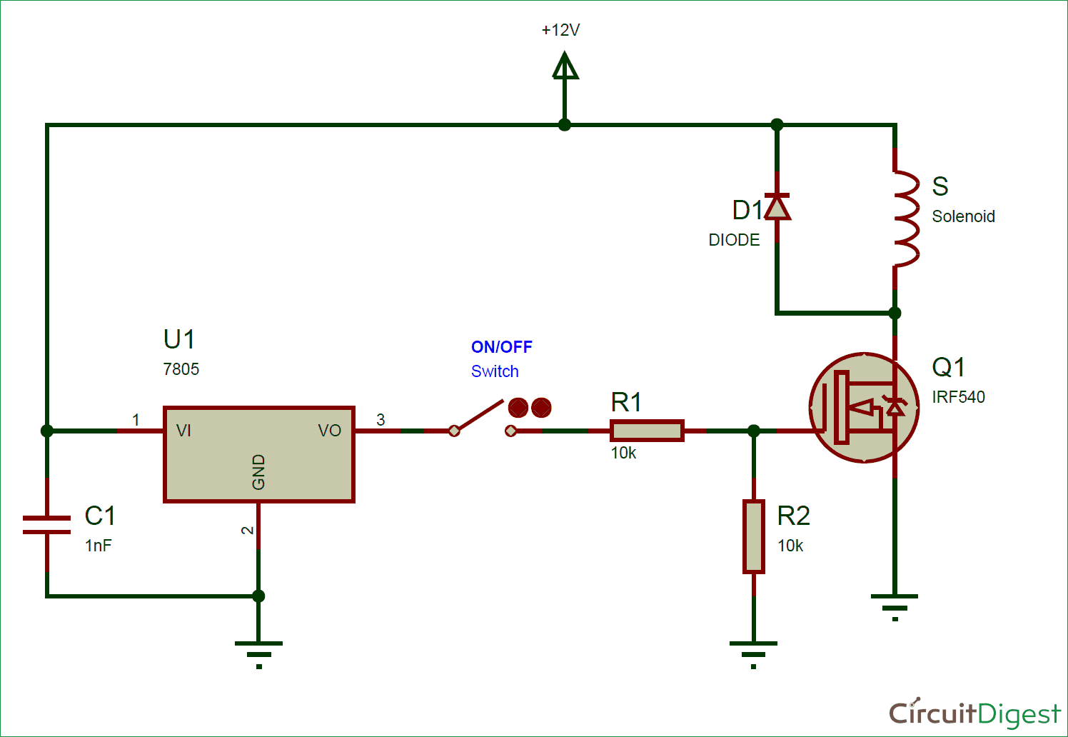
Solenoid Driver Circuit Diagram

Gm Solenoid Switch Wiring Diagram Wiring Diagram Solid Centre A Solid Centre A Leoracing It

Solenoid Valve Wiring

Diagram 3 Pole Solenoid Wiring Diagram Lawn Mower Full Version Hd Quality Lawn Mower Givediagram Italiadogshow It

Chevy Solenoid Wiring Wiring Diagram Hut Option Hut Option Trattoriadeicacciatorilecco It
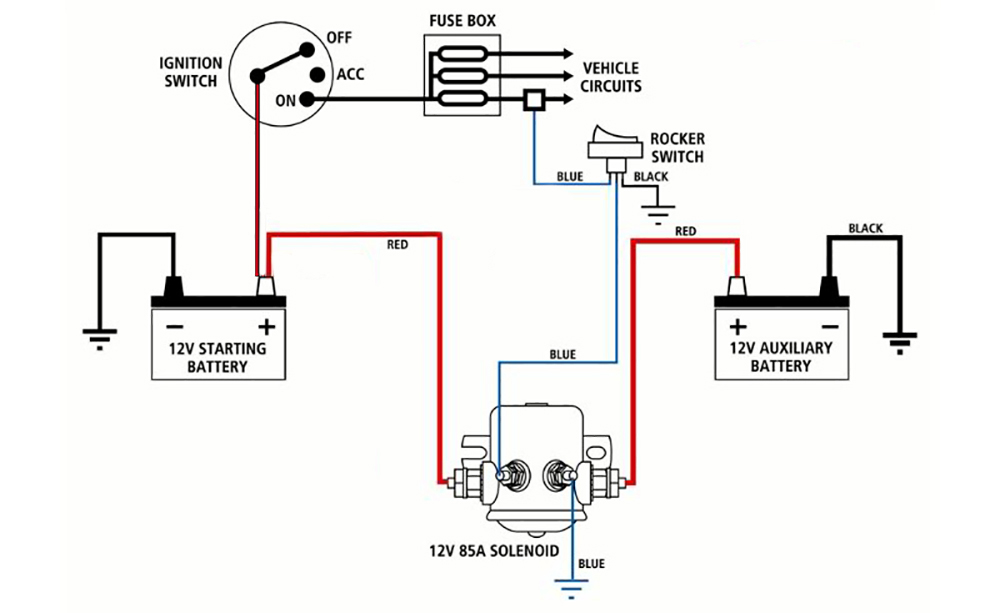
Diagram Dual Battery Solenoid Wiring Diagram Full Version Hd Quality Wiring Diagram Vetwiring Samanifattura It

Solenoid Switch Wiring Diagram Trusted Wiring Diagrams
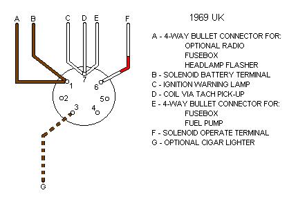
Ignition Switch Connections

Gm Solenoid Switch Wiring Diagram Wiring Diagram Solid Centre A Solid Centre A Leoracing It

Ford 3 Post Solenoid Wiring Diagram Wiring Diagram Rob Visual A Rob Visual A Miceincampania It

Mercruiser Solenoid Wiring Diagram Wiring Diagram Rung Manage Rung Manage Campusmelfi It

Diagram F150 Solenoid Wiring Diagram Schematic Full Version Hd Quality Diagram Schematic Sexdiagramfp Milanostoriadiunarinascita It

Briggs And Stratton Carburetor Solenoid Wiring Diagram
Http Www Drakecontrols Com Wp Content Uploads 15 05 Solenoid Wiring Manual A Pdf

Revival Universal Starter Solenoid With Main Fuse Installation Guide Revival Cycles
Diagram 3 Pole Solenoid Switch Wiring Diagram Full Version Hd Quality Wiring Diagram Guidecamz Scarpeskecherssport It

Solenoid Switch Wiring Diagram Electrical Plan Layout Meaning Air Bag Yenpancane Jeanjaures37 Fr
Cole Hersee Solenoid Wiring Diagram Cb550 Wiring Diagram Power Poles Yenpancane Jeanjaures37 Fr
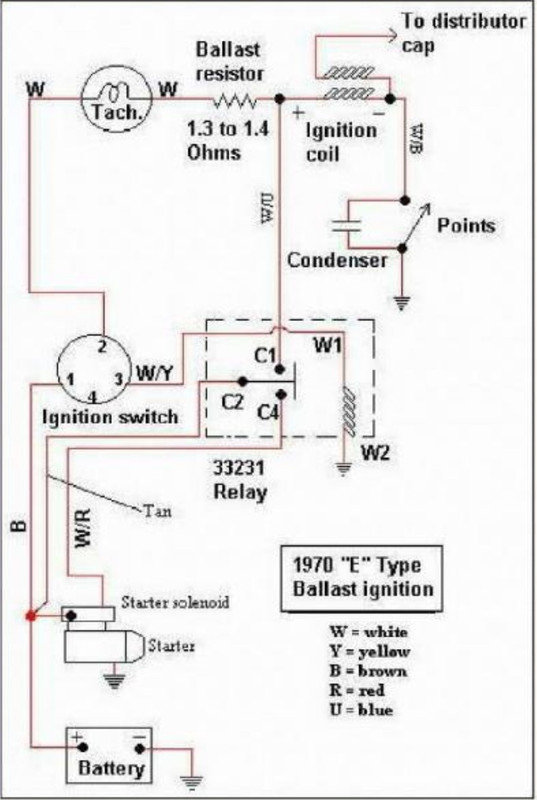
Starter Wiring And Solenoid Questions The E Type Forum

Diy Starter Remote Mount Solenoid Easy Step By Step How To With Schematic Youtube

3 Typical Car Starting System Diagram T X

Diagram 3 Pole Solenoid Wiring Diagram Lawn Mower Full Version Hd Quality Lawn Mower Givediagram Italiadogshow It

Ford Starter Solenoid Wiring Diagram Wiring Diagram Cycle Ignition Cycle Ignition Vicolo It

Point Motors Part 1 Solenoid Basics

Ford On Ford Solenoid And It Keeps All The Factory Connections At The Starter Starter Motor Starter Automotive Electrical

How To Wire A Solenoid Switch 4 Pole Starter Electric Problems
Wiring A Switch To Starter Solenoid On Dodge Wiring Diagram Calf Activity A Calf Activity A Miceincampania It

Linear Solenoid Actuator Theory And Tutorial

Wo 7632 Warn Winch Solenoid Wiring Diagram Albright Wiring Diagram
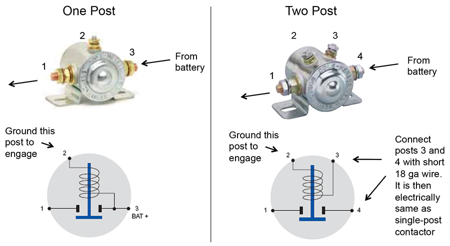
Aircraft Wiring

Wiring Diagram Electrical Wiring Diagram Electrical Winch Solenoid Electric Winch Winch

Sealed Solenoid Magnetically Operated High Voltage Electric Power Switch Diagram Schematic And Image 12

Starter Solenoid Wiring Diagram For Lawn Mower 2 Electrical Diagram Riding Lawn Mowers Lawn Tractor

Solenoid Control Relay Wiring Smith Co Electric
3

1992 Mustang Starter Solenoid Wiring Diagram Wiring Diagram Use Good Level Good Level Barcacciarredi It

Plc Wiring Diagram Solenoid Valve Diagram Page 1 Line 17qq Com
Gigglepin4x4 Net Ekmps Shops Dc8187 Resources Other 12v Pro Albright Wiring Diag Pdf

Schematic Circuit Diagram Of The Solenoid Switch Download Scientific Diagram
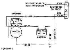
Fuel Shutoff Solenoid Wiring Diagram

Ignition Starter Wiring Diagram Wiring Diagram Crop Custom Crop Custom Immobiliareoikia It

Starter Solenoid The Definitive Guide To Solve All The Solenoid Problems

3 Typical Car Starting System Diagram T X

Lawn Tractor Solenoid Wiring Diagram Wiring Diagram Hear Leg A Hear Leg A Cfcarsnoleggio It
Q Tbn And9gctab7qwosryljrib0fyjuqautzpmjw9yv80xkoh Biiojowtjkb Usqp Cau
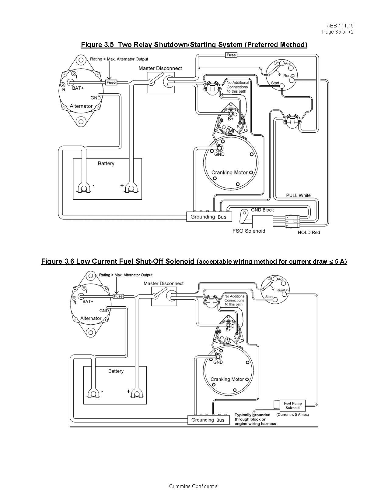
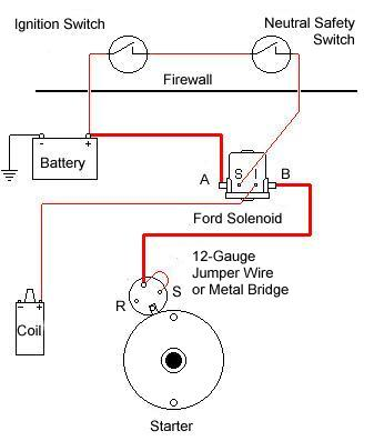
Basic Fuel Shutoff Solenoid And Starter Wiring Information Seaboard Marine

Starter Solenoid Wiring Diagram Deltagenerali Me Within Ford F150 Electrical Circuit Diagram Car Starter
Q Tbn And9gctajynnrbexlxouke9f8cfax5t0cung0pxdhfw2sfczqddjr0yv Usqp Cau
Diagram 12 Volt Solenoid Switch Wiring Diagram Full Version Hd Quality Wiring Diagram Avenndiagramz Host Eria It

Ford Starter Solenoid Wiring Diagram Wiring Diagram Cycle Ignition Cycle Ignition Vicolo It
Dna Knowledge Base Titan Solenoid In Cab Swtich Wiring Diagram

Chevy Solenoid Wiring Wiring Diagram Fund Query A Fund Query A Trattoriadeicacciatorilecco It

John Deere Solenoid Switch Wiring Diagram 97 Ford F 150 4 Way Trailer Wiring Diagram Peugeotjetforce Tukune Jeanjaures37 Fr

How To Wire Starter Button And Solenoid To An Atv 3 Wheeler 4 Wheeler Youtube

Mercury Ignition Switch Wiring Diagram Mercury Outboard Diagram Outboard
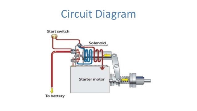
Solenoid Switch For Automobile

Solenoid Wiring Diagram Youtube
Ford Mustang 12 Volt Solenoid Wiring Diagram Wiring Diagram Grow Activity B Grow Activity B Miceincampania It
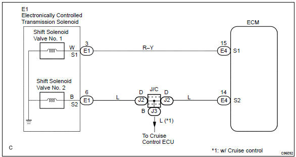
Toyota Corolla Repair Manual Circuit Description Shift Solenoid A Control Circuit Low High Electronic Controlled Automatic Transaxle Diagnostics

Schematic Circuit Diagram Of The Solenoid Switch Download Scientific Diagram

Wiring Ac Solenoid And Float Switch Reef Central Online Community
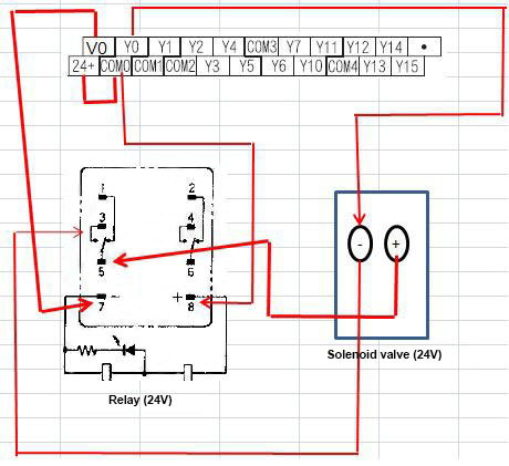
Plc Controls A Solenoid Valve With A Relay

Starter Solenoid Wiring Diagram Ignition Motorcycle Wiring Car Alternator Alternator Working

Starter Solenoid Wiring Diagram Starter Motor Ford Tractors Electrical Circuit Diagram
3
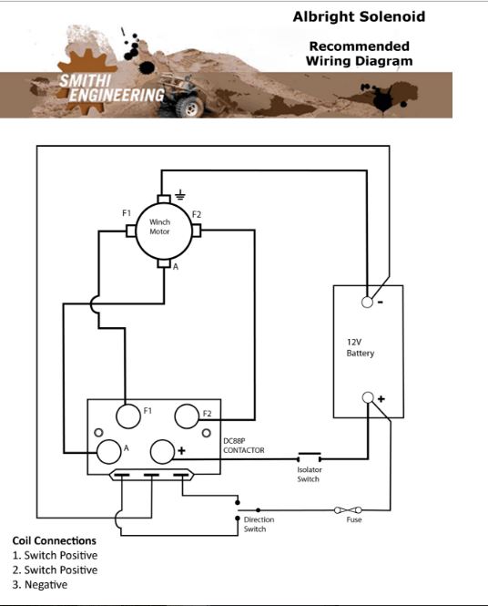
Shed Tech Albright Solenoid Wiring Diagram

Basic Electricity Tutorial Relays

Traditional Starter Control Structure 1 Battery 2 Ignition Switch Download Scientific Diagram

Double Pole Reversing Solenoid Jaycar Electronics

John Deere Tractor Solenoid Wiring Diagram Wiring Diagram Dat Justify Cut A Justify Cut A Tenutaborgolano It

Chevy Solenoid Wiring Diagram Wiring Diagram Suck Cable Suck Cable Campusmelfi It

Wiring A Solenoid Switch Machine

Diagram Chinese Atv Starter Solenoid Wiring Diagram Full Version Hd Quality Wiring Diagram 1gsuper Schematic Bellroma It

Fuel Shutoff Solenoid Wiring 101 Seaboard Marine

Diagram 8n Ford Tractor Starter Solenoid Wiring Diagram Full Version Hd Quality Wiring Diagram Jrschematicsn Artemisiacontemporanea It

Basic Ford Solenoid Wiring Diagram Wiring Diagram Hear Usage B Hear Usage B Agriturismoduemadonne It
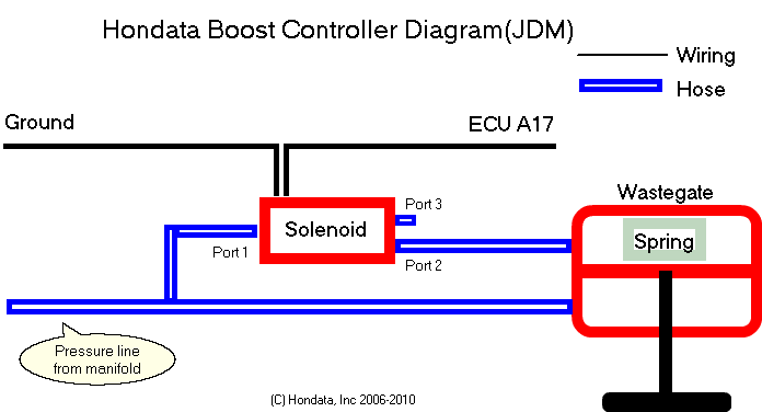
Hondata S300 Programmable Ecu Guide
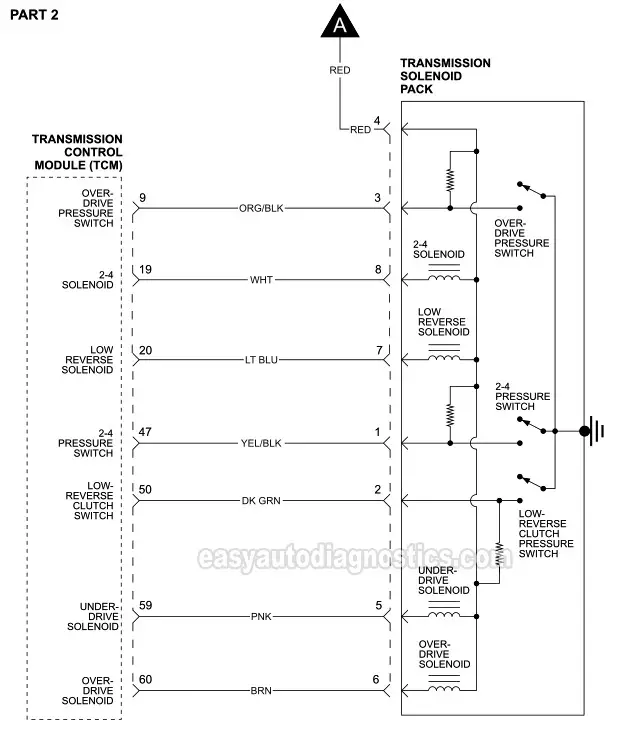
Transmission Solenoid Pack Circuit Wiring Diagram 1996 1998 3 8l Chrysler Dodge Mini Van
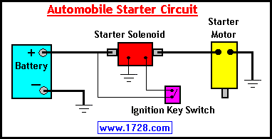
Basic Electricity Tutorial Relays

Chevy Solenoid Wiring Diagram Wiring Diagram Desc Mug Ready A Mug Ready A Fmirto It

3 Typical Car Starting System Diagram T X

Diagram 1942 Ford Solenoid Wiring Diagram Full Version Hd Quality Wiring Diagram Ardiagramlg Mercatutto It
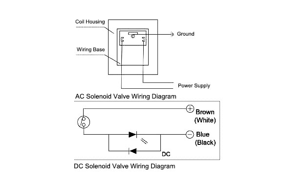
How To Wire A Solenoid Valve

Ford Starter Solenoid Wiring Wiring Diagram Use Pipe Land Pipe Land Barcacciarredi It

Starter Solenoid The Definitive Guide To Solve All The Solenoid Problems

Cj Jeep Starter Solenoid Wiring Wiring Diagram Solid Centre A Solid Centre A Leoracing It
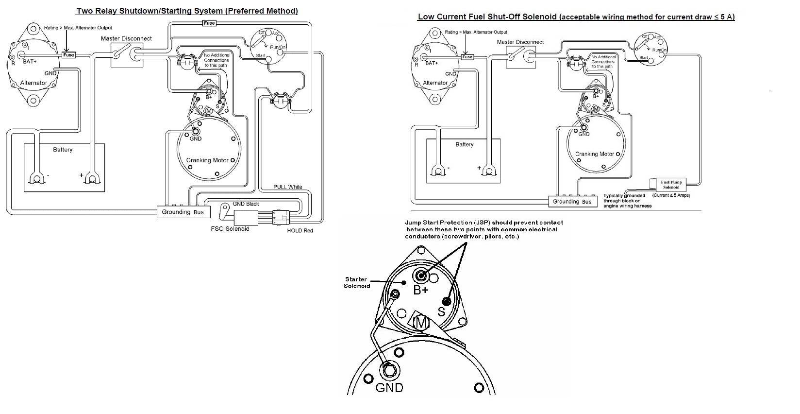
Basic Fuel Shutoff Solenoid And Starter Wiring Information Seaboard Marine

Ford Solenoid Wiring Diagram Sbc Wiring Diagram Arch Advance Arch Advance Immobiliareoikia It

Solved I Need A Ford F150 Solenoid Diagram So I Can Hook It Up Fixya
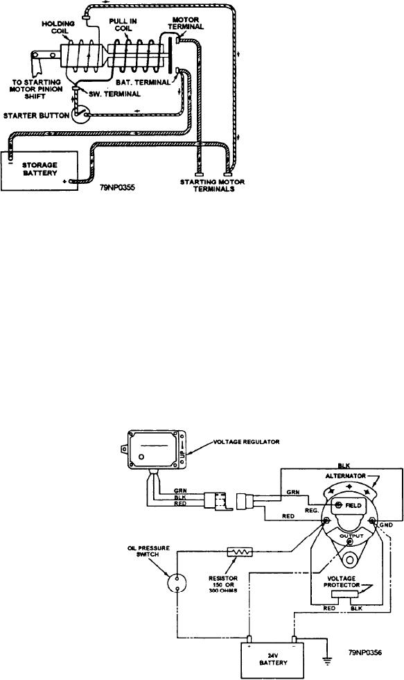
Figure 5 6 Solenoid Switch Diagram
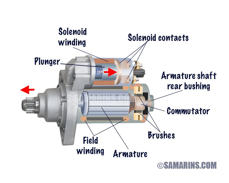
Starter Motor Starting System How It Works Problems Testing

Diagram 4 Post Solenoid Wiring Diagram Full Version Hd Quality Wiring Diagram Ardiagramlg Mercatutto It
3 Post Starter Solenoid Wiring Diagram Wiring Diagram Networks
Chevy Solenoid Wiring Diagram Wiring Diagram Close Update B Close Update B Prevention Medoc Fr
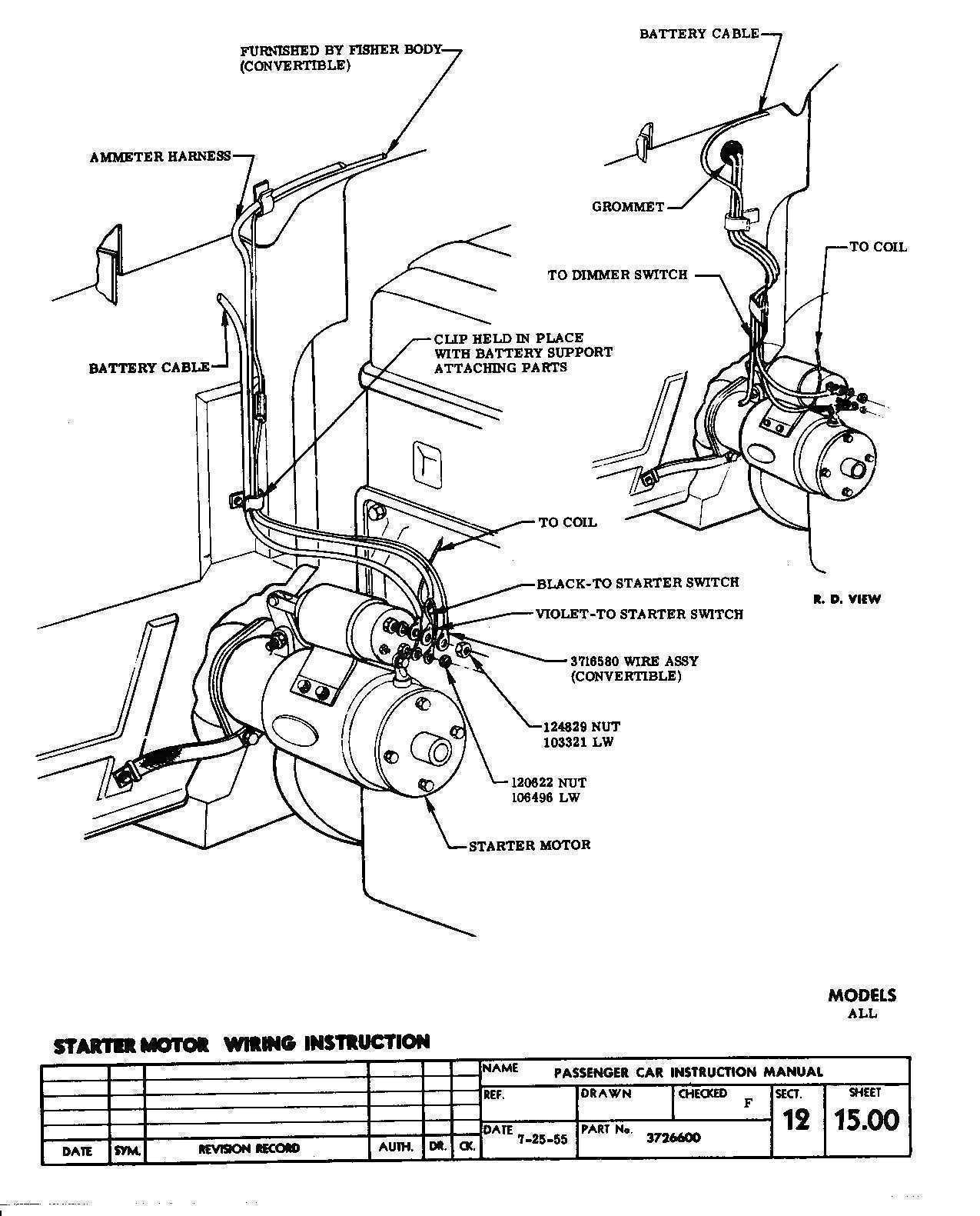
Chevy Solenoid Wiring Diagram Wiring Diagram Suck Cable Suck Cable Campusmelfi It
Http Www Drakecontrols Com Wp Content Uploads 15 05 Solenoid Wiring Manual A Pdf
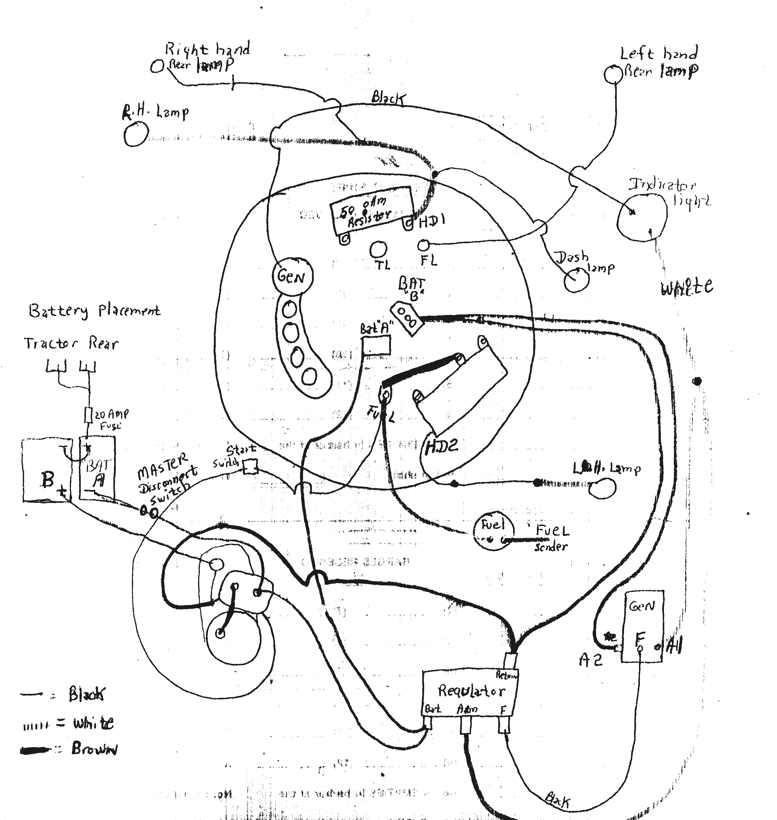
24v Starter Solenoid Wiring Diagram Kfx 450r Wiring Diagram For Begeboy Wiring Diagram Source

Solenoid Testing Corsa Performance Marine
Gigglepin4x4 Net Ekmps Shops Dc8187 Resources Other 12v Pro Albright Wiring Diag Pdf

Yanmar Solenoid Wiring Diagram Wiring Boat Wiring Trailer Wiring Diagram Kill Switch
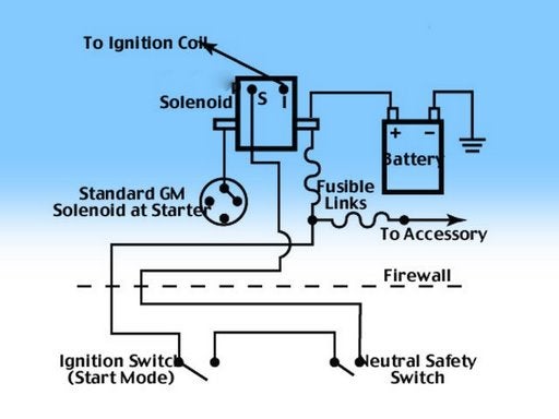
Remote Ford Solenoid For Gm No Hot Start


